
Executive Summary
Reverse engineering and modifying hard drive firmware sounds exotic, but the primitives turn out to be surprisingly accessible once you know where to look. In this first installment, security researcher Ryan Miceli walks through the complete workflow for three drive models — Western Digital WD3200BEVT, Samsung PM871a SSD, and Samsung HM020GI — covering how he obtained firmware images (PC-3000 forum dumps, OEM update utilities), parsed proprietary binary formats, decoded a modified LZHUF compression scheme, deobfuscated a Samsung SSD firmware, and loaded everything into IDA Pro for analysis.
The most striking part of the post is the live JTAG debugging session: by soldering wires to an unpopulated MICTOR connector on the WD PCB, Miceli connected OpenOCD via FT232, set memory-access breakpoints, and traced vendor-specific “backdoor” SMART commands all the way up to the DMA READ EXT handler — which turned out to live in a service-area overlay module loaded at boot rather than in the main firmware image. Once located, he hot-patched the overlay in RAM with an ARM Thumb trampoline that spins for ~450 ms per sector read, enough to dial in a race-condition exploit targeting the Xbox 360 console. Part 2 will cover AI-assisted firmware analysis on the same drives.
Background
The project originated from an Xbox 360 exploit that required a carefully timed race condition during HDD reads. The window between when the console issued a read request and when the drive responded needed to be stretched by a few hundred milliseconds. The initial plan was to patch HDD firmware to insert an artificial delay for a specific sector, buying enough time for the exploit payload to execute. Although alternative ways to tune the race condition were ultimately found without touching the drive, the firmware experimentation proved rewarding enough to document in full.
Prior research on HDD firmware modification existed but was scattered — mostly forum posts 15 or more years old, often describing drives no longer in production or containing outright errors. Enough fragments were accurate, however, that a coherent attack plan gradually assembled from them. The goal for each drive was the same: dump or acquire the firmware, load it into a disassembler, find the read-request handler, and patch in a delay.
The Test Subjects
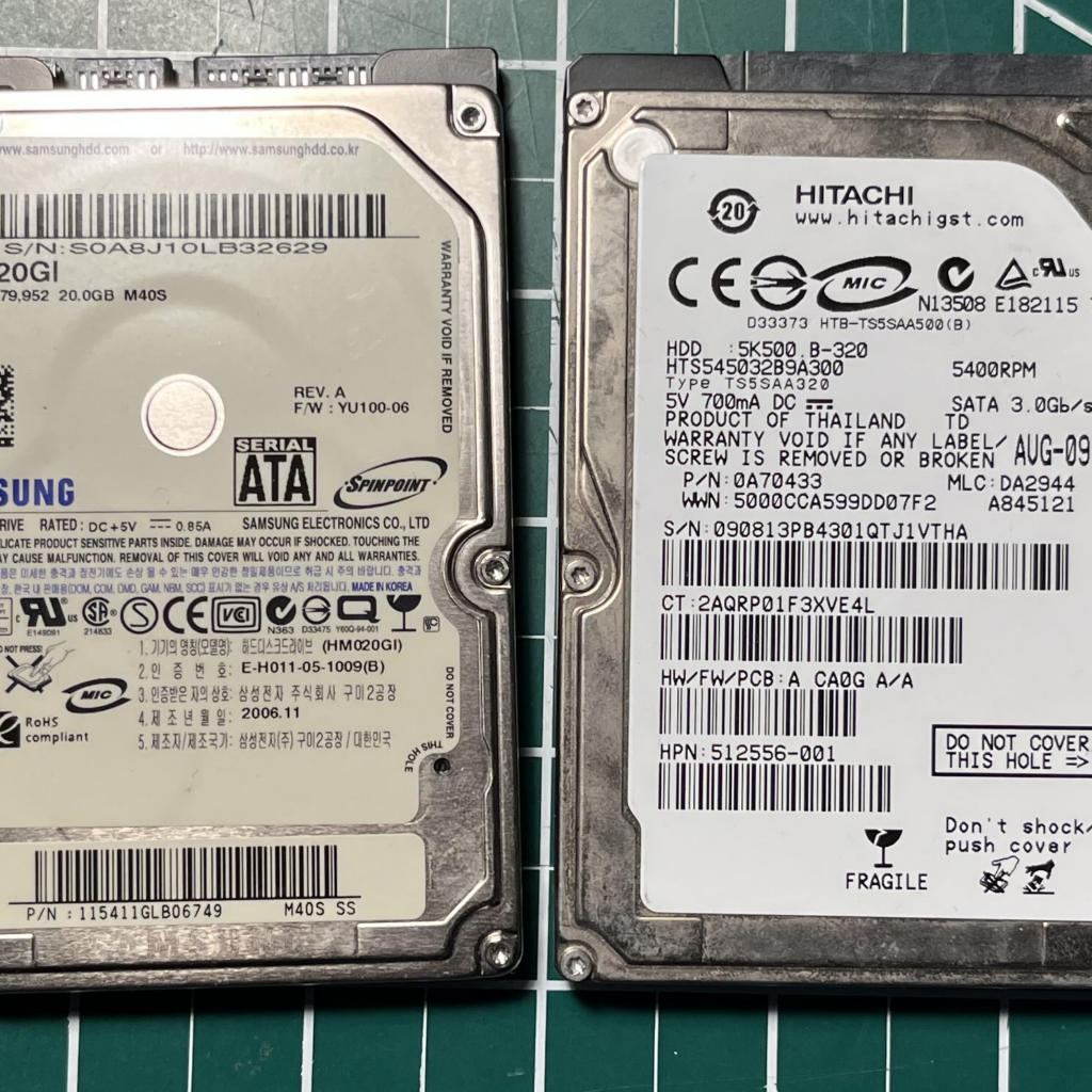
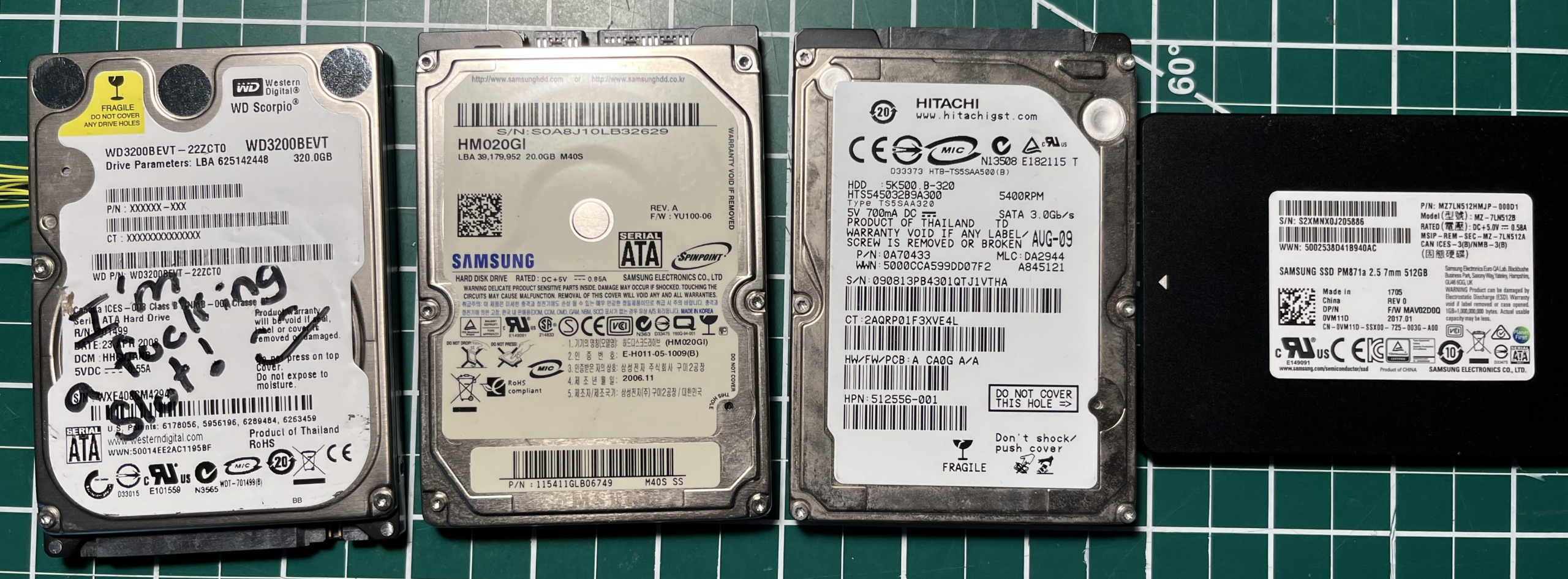
The initial target was any drive that could serve the Xbox 360 exploit — meaning models commonly found in Xbox 360 consoles. A Western Digital drive was added because of known backdoor vendor commands enabling low-level memory and service-area access. A pair of Samsung drives rounded out the collection, one HDD and one SSD.
- Samsung HM020GI
- Hitachi HTS545032B9A300
- Western Digital WD3200BEVT
- Samsung PM871a
Spinning Up
Before writing any code, the author spent time reading through HDD Guru forum archives and a blog series by MalwareTech who had attempted similar work on a different model. A resonant observation from that series:
“Before i started hacking I’d decided to read other people’s research to get a good idea of where to start. Resourceful, right? Well it actually turns out that most of the research I’ve based mine on was either wrong or just doesn’t apply to this hard disk.”
MalwareTech
That matched the experience exactly. For each drive, the research sequence was:
- Obtain a firmware dump — found online or pulled directly from the drive.
- Load the firmware into IDA Pro and work around any compression or encryption. Without analysis capability, patching is impossible.
- Identify a viable path to flash modified firmware back — standard ATA command, vendor backdoor, or physical chip programmer. Without a write path, the drive is a dead end.
- Find the code handling the DMA READ EXT command, likely via a command-handler function table somewhere in the firmware.
- Write patches to introduce a delay when a specific sector is read.
- Flash the modified firmware and test.
Obtaining the Drive Firmware
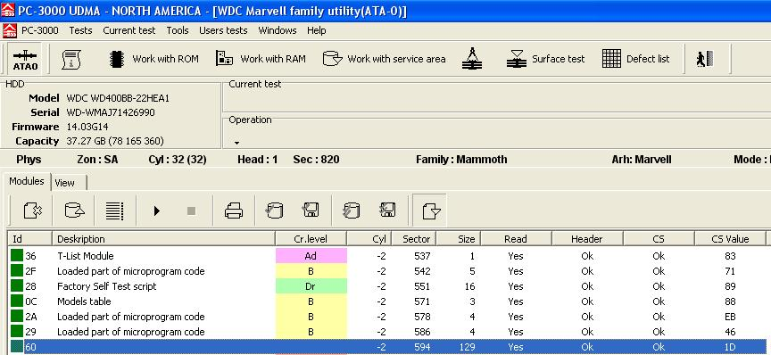
Sources varied by drive model. The WD firmware image was found on HDD Guru, where community members post dumps obtained with PC-3000 professional data-recovery tooling. The Samsung HM020GI dump came from a Twitter contact with PC-3000 access. The Samsung PM871a firmware was sourced from a Lenovo OEM update utility — a double win, since reverse engineering the updater also revealed the exact ATA commands needed to flash new firmware. The Hitachi drive yielded nothing useful and was set aside.
Western Digital
Forum posts described the general layout of the WD firmware image, confirmed by a brief hex-editor session: a flat file starting with section headers followed by data blocks, each with an 8-bit summation checksum. An IDA loader plugin was written to parse this layout — at which point it became apparent that all sections except the first were compressed.
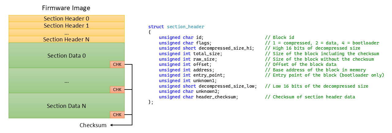
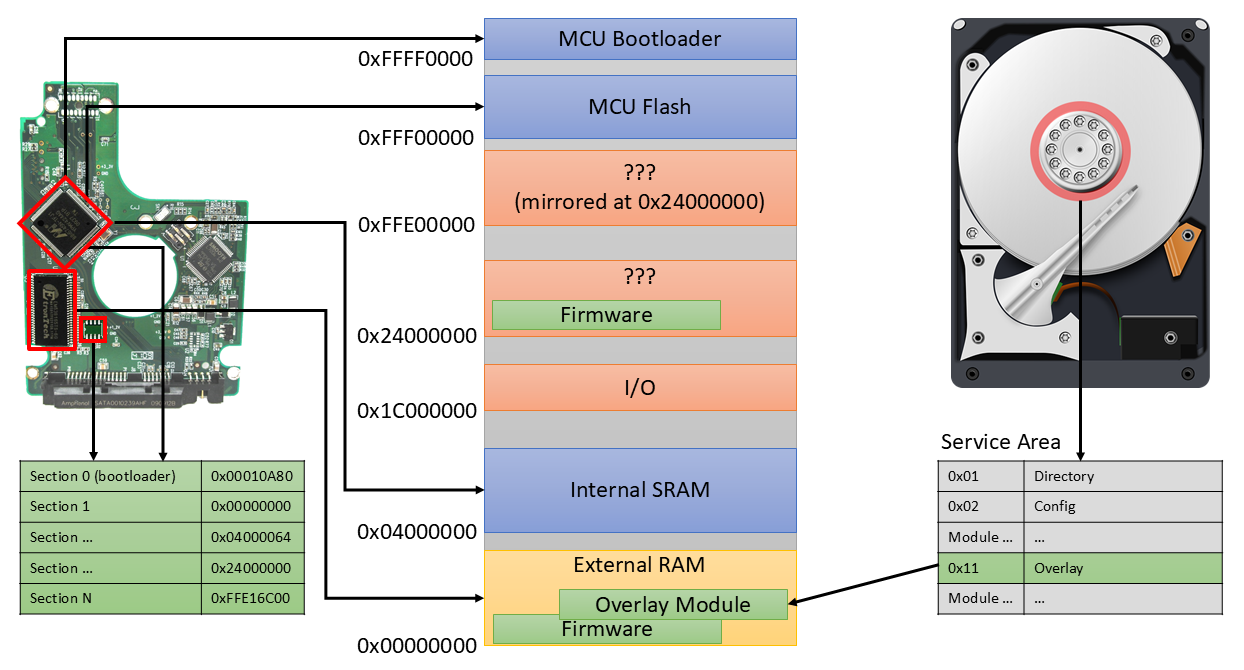
The first section is a loader stub: the MCU bootloader copies it into RAM and executes it, and this stub decompresses and maps all remaining sections to their correct base addresses. Running a compressed block through algorithm-detection tools produced no match, so the first section was loaded into IDA as ARM code and reverse engineered directly. After labeling the section-loading loop and identifying the decompression function, the algorithm turned out to be LZHUF — but with two non-standard constants: the ring-buffer size N was changed from 2048 to 4096, and the run-length calculation subtracts THRESHOLD rather than adding it, explaining why automated detection failed.
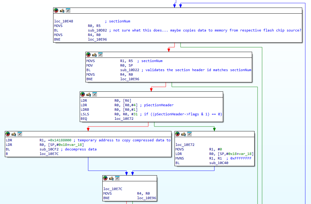

After updating the IDA loader to apply the correct decompression, the complete WD firmware loaded with all sections at proper base addresses and was ready for analysis.
Samsung PM871a
The PM871a firmware was obtained from Lenovo’s support site as part of an update utility covering roughly two dozen Samsung SSD models. The strategy of hunting OEM update utilities generalizes well: the utility typically decrypts or deobfuscates the firmware before sending it to the drive, providing both the plaintext firmware image and the flash commands in one package.
The PM871a firmware was obfuscated with a simple nibble-manipulation algorithm, reverse engineered from the updater:
void DecodeFirmware(unsigned char* pBuffer, unsigned int Length)
{
    // Loop through the entire firmware buffer.
    for (unsigned int i = 0; i < Length; i++)
    {
        // Get the hi nibble for the current byte.
        unsigned char nibbleHi = (pBuffer[i] >> 4) & 0xF;

        // Do bit twiddling?
        if ((nibbleHi & 1) != 0)
            nibbleHi >>= 1;
        else
            nibbleHi = 0xF - (nibbleHi >> 1);

        // Mask in the new hi nibble value.
        pBuffer[i] = (pBuffer[i] & 0xF) | (nibbleHi << 4);
    }
}
After deobfuscation, a suspicious 28-byte run appeared at the very beginning of the file, differing between two firmware versions (one for the 2.5″ SATA form factor, one for M.2). The rest of the files differed only in minor code and data patches, suggesting no strong public-key signature over the full image. A 28-byte block could be SHA-224 or a truncated SHA-256, but the large regions of identical bytes between versions made RSA/ECDSA unlikely.
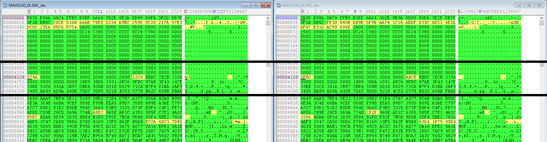
Loading the deobfuscated image into IDA as a flat binary immediately revealed multiple sections at distinct base addresses. The first 8 KB appeared to be metadata; after that, byte sequences that clearly looked like memory addresses began to appear:

The address values aligned with the ARM Cortex-M3 memory map:
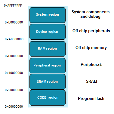
Further analysis showed that section offsets and sizes are expressed in 16 KB block units. An IDA loader incorporating this produced a fully mapped firmware image.
Samsung HM020GI
The HM020GI firmware dump showed visible plain-text strings mixed with what looked like machine code, but no standard architecture disassembled the bytes correctly. The entire file appeared to be word-flipped:

Whether this is an exotic ISA, custom bytecode for an on-chip VM, or something else entirely remained unresolved. The HM020GI was set aside for Part 2, where AI-assisted black-box analysis will be applied.
Flashing Modified Firmware
From this point, the article focuses exclusively on the Western Digital WD3200BEVT. Three general methods exist for writing new firmware to a drive:
- The standard DOWNLOAD MICROCODE ATA command.
- Backdoor vendor commands — used for repair and diagnostics, or on drives that rely on service-area overlays for firmware patches.
- A physical serial interface exposed on the drive PCB — also a repair/diagnostics path.
DOWNLOAD MICROCODE Command
The ATA specification defines a DOWNLOAD MICROCODE command for uploading new firmware. The host sends the command with register values indicating firmware size, streams the firmware in chunks or via DMA, and the drive validates and writes it to non-volatile storage. A successful update requires a power cycle. A failed update may leave the drive inoperable, though recovery is usually possible with low-level access. All consumer OEM update utilities use this command under the hood.
Back Door Vendor Commands
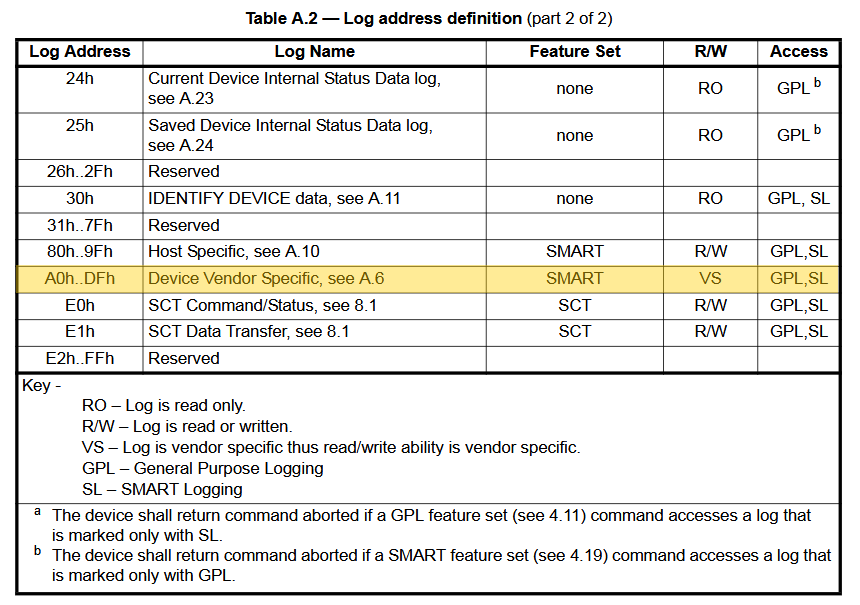
Many older Western Digital drives received incremental firmware patches via service-area overlay modules — special code stored in a hidden region of the platters and loaded into RAM at boot — rather than through full DOWNLOAD MICROCODE updates. Reading and writing these modules is possible through vendor-specific extensions to the SMART READ/WRITE LOG ATA command. Log address 0xBE (in the vendor-defined range per the ATA spec) is the gateway to WD’s repair and diagnostics command set.
Physical Serial Interface
Most HDDs expose a 4-pin RS232 serial port next to the SATA connector. Connecting to it enables diagnostic and repair commands specific to each drive model. This interface was left for Part 2.
The Western Digital SPI Flash
The primary plan for reflashing the WD drive was to use the SMART backdoor vendor commands. The concern was that early patches would almost certainly corrupt the drive’s ability to boot or accept further reflashing, creating a brick that the backdoor commands could not recover from.
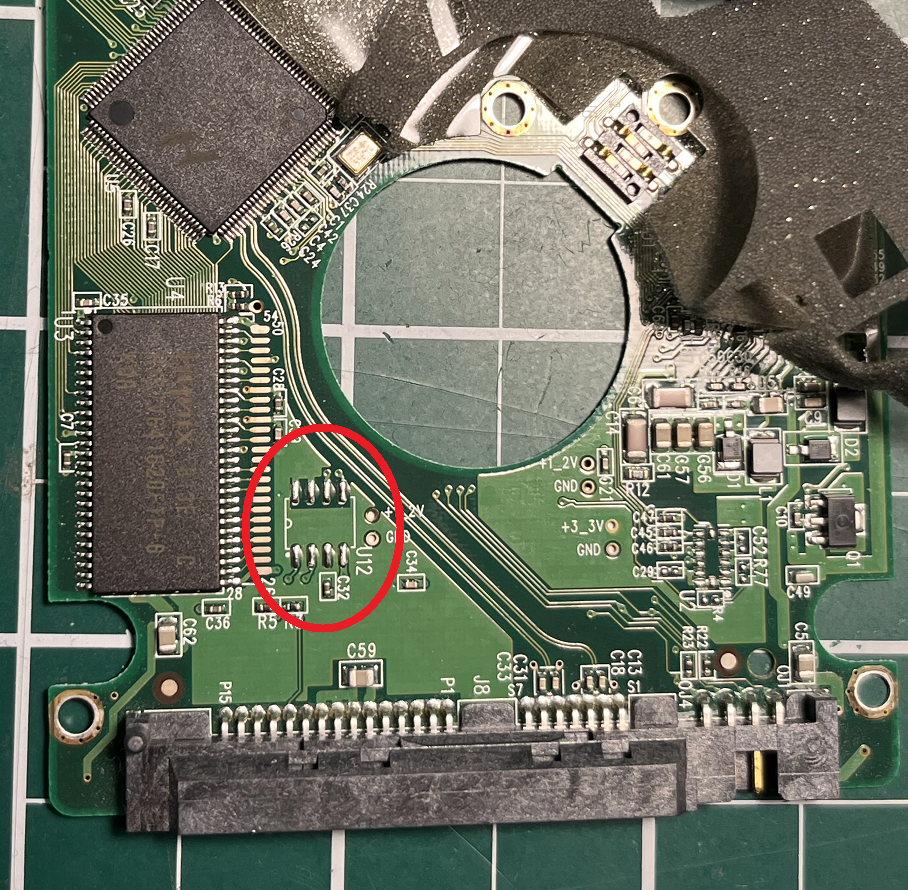
WD drives store their primary firmware either in internal MCU flash or in an external SPI flash chip. The specific model relied on internal MCU flash, but the PCB included unpopulated pads for an SPI flash chip and two resistors that signal the MCU to boot from it instead. Soldering in a compatible SPI flash chip meant that any bad flash could be recovered by directly reprogramming the chip with an external programmer, in-circuit, without needing the drive to function.
Analyzing the Firmware
Finding the DMA READ EXT handler was the hardest part. The WD firmware contains no helpful strings, is split across many memory segments some of which are absent from the flat image file, and relies on runtime-loaded overlay modules for key functionality. Getting to the relevant code required JTAG hardware debugging, vendor-specific memory read commands, and careful tracing through indirect function tables.
You Ever Debug a Hard Drive Before?
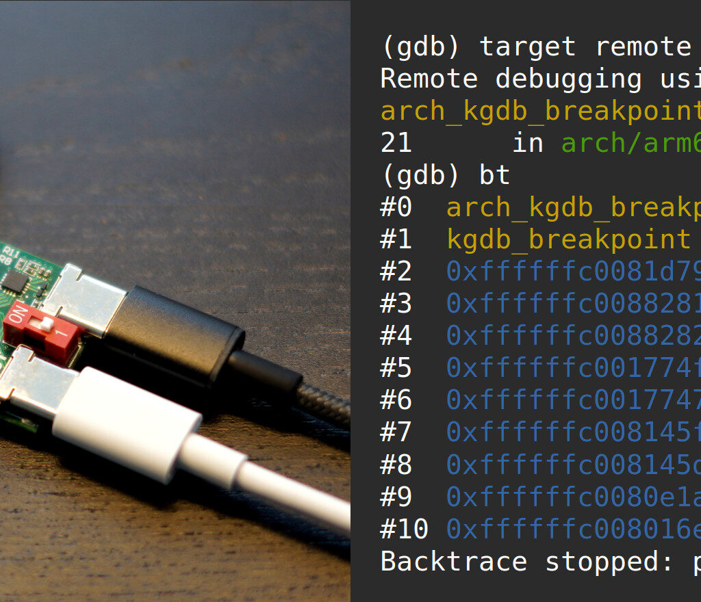
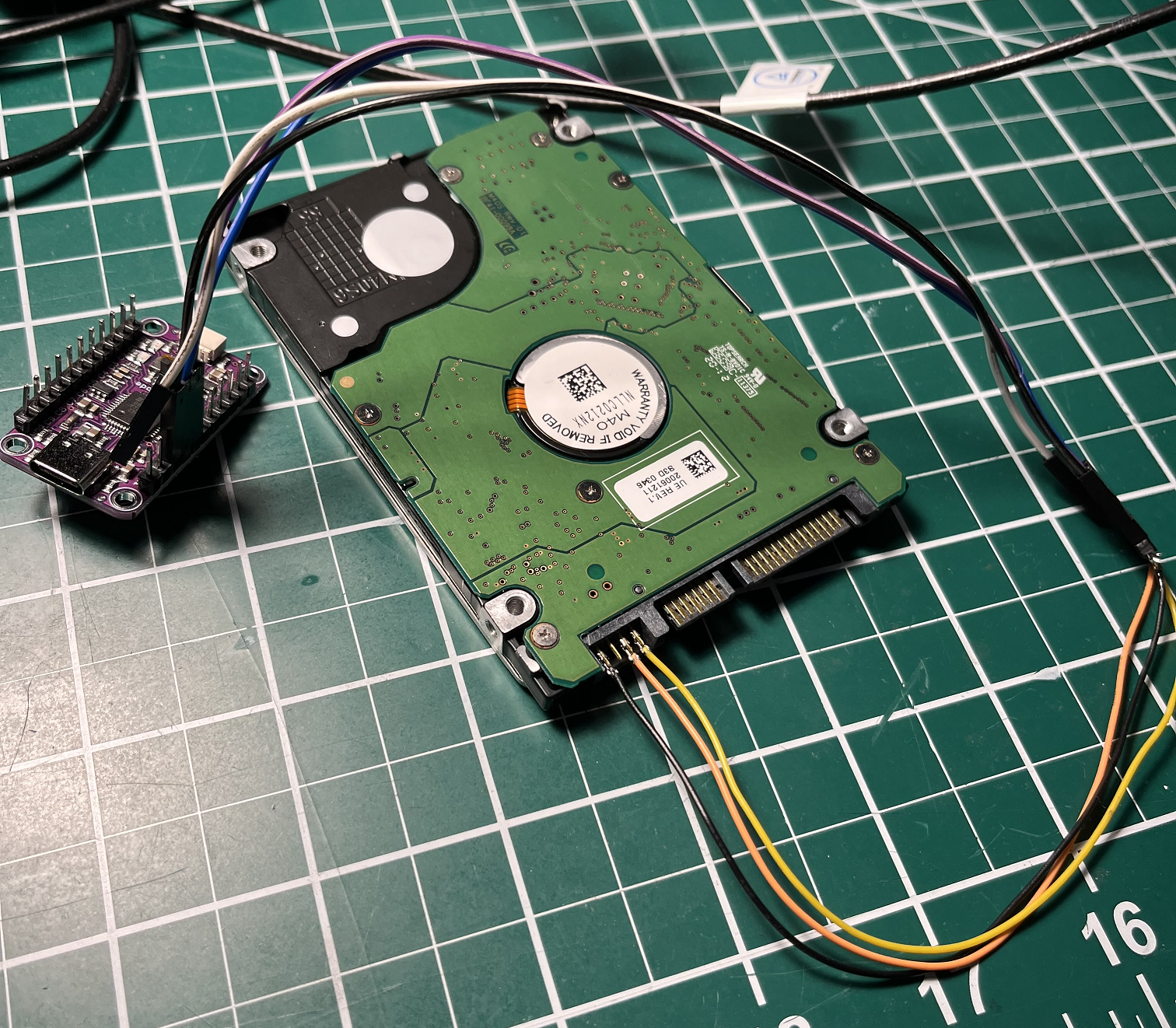
Most WD drives include an unpopulated 38-pin MICTOR connector on the PCB for JTAG access to the MCU. A few wires soldered to those pads provided hardware-level debugging: the ability to set breakpoints, inspect registers and memory, and step through execution while sending ATA commands from a connected PC.
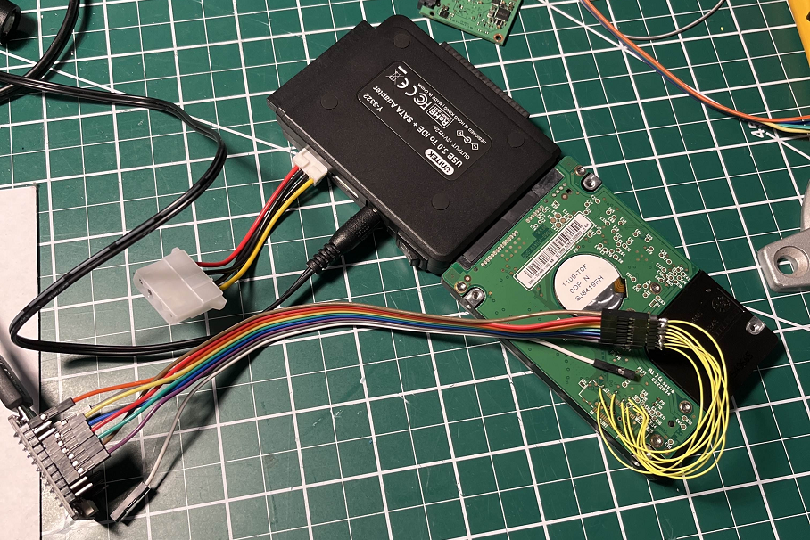
Working constraints made this non-trivial. The drive had to be connected to a Windows PC via SATA (no USB adapter with ATA passthrough support was available). If the drive stopped responding, Windows declared it missing and blocked further commands until a reboot. Occasionally the drive required a power cycle after being put into an unexpected state by the debugger. Since this was the author’s first JTAG experience, the setup involved considerable trial and error with OpenOCD and an FT232 adapter before a stable connection was established.
Vendor Specific Commands
The WD backdoor includes a Read RAM VSC (vendor-specific command) that returns an arbitrary region of MCU memory. The plan: set a hardware memory-access breakpoint at an arbitrary address (0x41414141), then issue the Read RAM VSC with that address. When the breakpoint fires, the call stack leads back to the VSC dispatcher, which should sit near the main ATA command dispatcher — and from there, to the DMA READ EXT handler.
Issuing a VSC requires an ATA passthrough request — a host-accessible structure that programs ATA port registers directly and optionally transfers a data sector alongside:
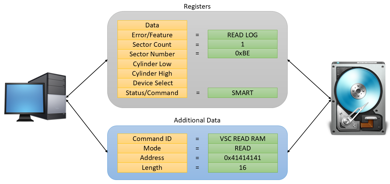
The following C function constructs and issues a VSC via IOCTL_ATA_PASS_THROUGH:
bool SendVSCAccessKey(HANDLE hDrive, BYTE bVscCmd, bool bWriteAccess, DWORD dwAddress = 0, DWORD dwSize = 0)
{
    DWORD BytesRead = 0;
    DWORD BufferSize = sizeof(ATA_PASS_THROUGH_EX) + 512;
    BYTE abPassthroughData[sizeof(ATA_PASS_THROUGH_EX) + 512] = { 0 };
    ATA_PASS_THROUGH_EX* pAtaPassthrough = (ATA_PASS_THROUGH_EX*)abPassthroughData;
    VSC_COMMAND_DATA* pVscCommand = (VSC_COMMAND_DATA*)(pAtaPassthrough + 1);

    // Setup the passthrough data:
    pAtaPassthrough->Length = sizeof(ATA_PASS_THROUGH_EX);
    pAtaPassthrough->AtaFlags = ATA_FLAGS_DATA_OUT;
    pAtaPassthrough->TimeOutValue = 5;
    pAtaPassthrough->DataTransferLength = 512;
    pAtaPassthrough->DataBufferOffset = sizeof(ATA_PASS_THROUGH_EX);

    // Setup port registers for SMART WRITE LOG command:
    IDEREGS* pRegs = (IDEREGS*)pAtaPassthrough->CurrentTaskFile;
    pRegs->bCommandReg = ATA_OP_SMART;
    pRegs->bFeaturesReg = SMART_WRITE_LOG;
    pRegs->bSectorCountReg = 1;
    pRegs->bSectorNumberReg = 0xBE;     // Special WD log address
    pRegs->bCylLowReg = 0x4F;
    pRegs->bCylHighReg = 0xC2;
    pRegs->bDriveHeadReg = 0xA0;

    // Setup the VSC command data:
    pVscCommand->CommandId = bVscCmd;
    pVscCommand->Mode = bWriteAccess == true ? VSC_MODE_WRITE : VSC_MODE_READ;
    pVscCommand->ReadWriteRam.Address = dwAddress;
    pVscCommand->ReadWriteRam.Length = dwSize;

    // Send the command to the drive.
    if (DeviceIoControl(hDrive, IOCTL_ATA_PASS_THROUGH, pAtaPassthrough, BufferSize,
        pAtaPassthrough, BufferSize, &BytesRead, nullptr) == FALSE)
    {
        wprintf(L"SendVSCAccessKey failed 0x%08x\n", GetLastError());
        return false;
    }

    // Check for any errors.
    OUT_REGS* pOutRegs = (OUT_REGS*)pAtaPassthrough->CurrentTaskFile;
    if ((pOutRegs->bStatusReg & 1) != 0)
    {
        wprintf(L"SendVSCAccessKey failed drive returned 0x%04x\n", WD_ERROR_CODE(pOutRegs));
        return false;
    }
    return true;
}
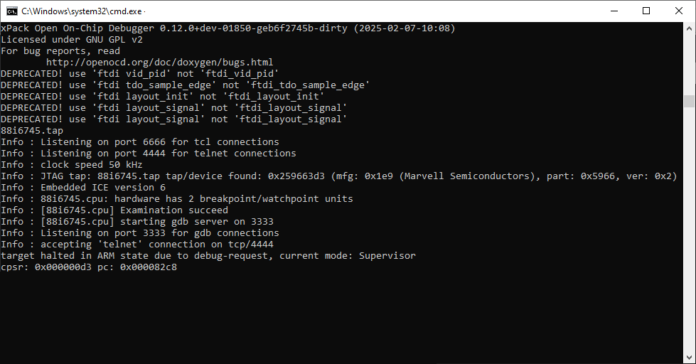
With a memory-access breakpoint set at 0x41414141 and the test app running, the breakpoint fired. OpenOCD connected successfully:
Into the Belly of the Beast
With the debugger broken in, the register dump showed the faulting instruction at address 0xFFE1D780 inside firmware code:
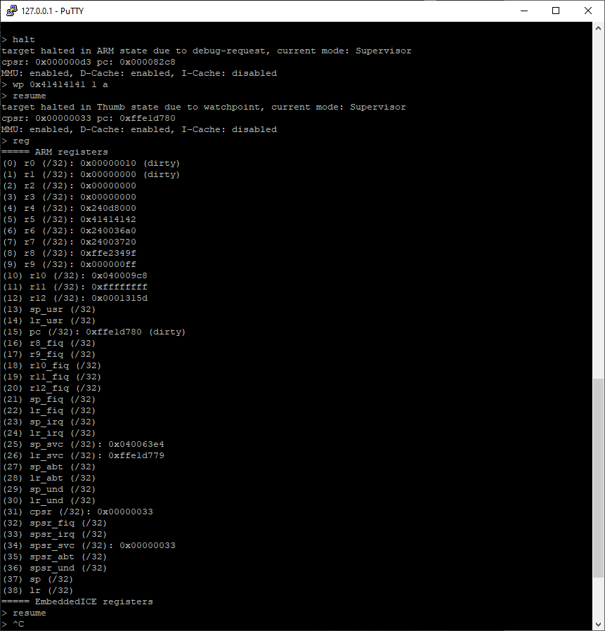
0xFFE1D780 inside WD firmware. Source: original article.Analysis of the function at that address revealed how it loaded VSC parameters from the command buffer and executed the memory read:
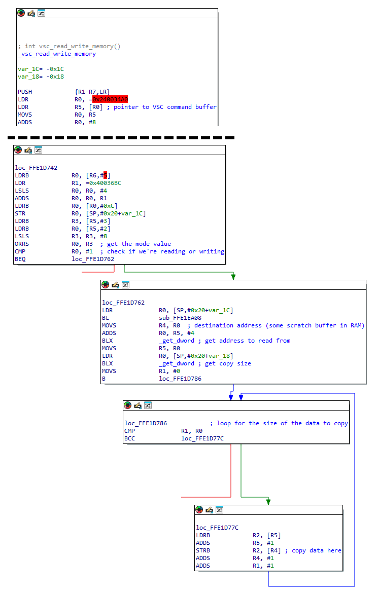
_vsc_read_write_memory). Source: original article.Tracing up the call stack led to a 67-entry VSC lookup table:
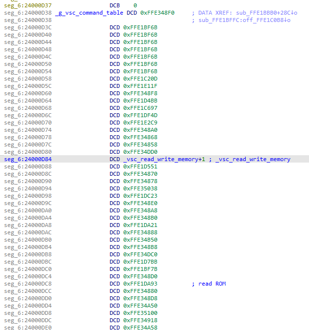
Further memory inspection revealed a 40-element array (each element 16 bytes) used pervasively throughout the firmware. After dumping it and scripting a parser, each element appeared to carry a data pointer in the first field and a function pointer in the second — a request dispatch table. Some function pointers matched addresses already identified in the VSC call chain:
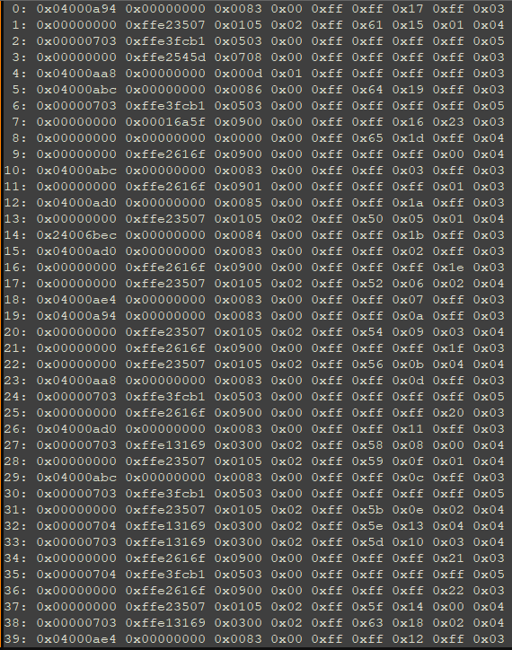
To identify which entry handled DMA READ EXT requests, the test app was modified to issue approximately two dozen sector reads in rapid succession, “poisoning” the array with active request entries. The array dump afterward showed a distinct new function pointer in one slot:

A breakpoint on that function confirmed it triggered on sector reads. One catch: the address did not fall within any range in the firmware image.
Where the FSCK Is This Code?
The sector-read handler lived in service-area overlay module 0x11, loaded into RAM after the main firmware bootstrap completed. The WD boot sequence: MCU bootloader → decompresses and maps firmware sections → loads overlay modules from the service area into RAM at their designated addresses. Because the overlay is runtime-loaded, patching it means working entirely in memory rather than in the flat firmware file. The region was dumped from live RAM once the drive was fully booted:
Patching the Firmware
Since the target code lives in a RAM-resident overlay, patching it in-memory via VSC write commands was the safest approach: iterate on the patch until it worked, then worry about persisting it to the service area. The overlay dump was loaded into IDA for analysis.
The main read handler sub_16A5E drives a loop over the 40-element SATA request array. Each iteration calls sub_1671C, which handles the individual request. The loop continues as long as the Unk4 field of the current entry is not 0xFF — suggesting large read requests may be split into multiple sub-requests. The hook was placed a few instructions into sub_1671C:
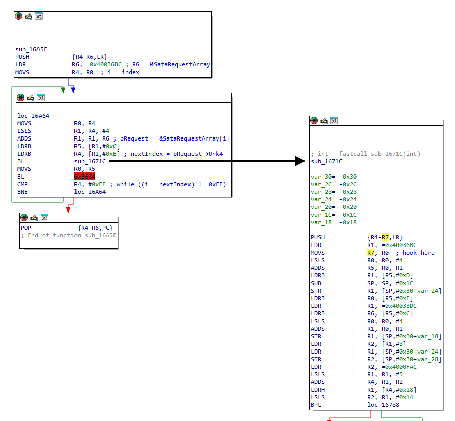
sub_1671C. Source: original article.The patch is an ARM Thumb trampoline: instructions at the entry of sub_1671C are replaced by a branch to a code cave in unused RAM, which spins for approximately 200 ms before trampolining back via re-execution of the overwritten instructions:
.syntax unified
# Timing related variables to control the delay:
.set F_CPU,                 10000000        # CPU frequency
.set MS_DELAY,              200             # 200ms delay

# ============================================================================
# Our code cave
# ============================================================================
    .long 0xFFEAB600
    .long (9f - 0f)
0:
        # Call our hook.
        push    {r0-r7, lr}
        blx     Hook_SataDmaRead
        pop     {r0-r7, lr}
        # Replace instructions we overwrote.
        movs    r7, r0
        lsls    r0, r0, #4
        adds    r5, r0, r1
        ldrb    r1, [r5, #0xD]
        sub     sp, sp, #0x1C
        str     r1, [sp, #0xC]
        ldrb    r0, [r5, #0xE]
        # Trampoline back.
        ldr     lr, =0x0001672E+1
        bx      lr
    Hook_SataDmaRead:
        # Setup delay counter.
        ldr     r3, =(MS_DELAY * F_CPU / 1000)
    Hook_SataDmaRead_loop:
        # Spin until the counter is 0.
        sub     r3, r3, #1
        bne     Hook_SataDmaRead_loop
        bx      lr
        .pool
9:
# ============================================================================
# Hook the sata DMA request handler
# ============================================================================
    .long 0x00016720
    .long (9f - 0f)
0:
        .thumb_func
        ldr     r7, =0xFFEAB600
        bx      r7
        .pool
9:
.long 0xFFFFFFFF
Task Failed Successfully
To validate the patch, the test app read a specific sector 10 times (averaging elapsed time), wrote the patch to RAM, then repeated the 10-read cycle. Results:
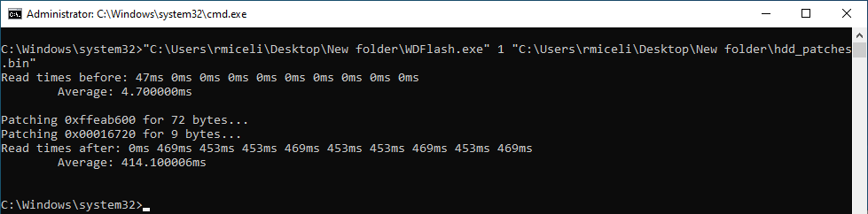
The delay landed at roughly 450 ms rather than 200 ms — the spin-loop math was back-of-envelope rather than calibrated. Most clean-run read times showed 0 ms (cache hits), and the first delayed read was also 0 ms for the same reason. All remaining delayed reads were consistently above 400 ms, exactly what was needed.
With the patch validated, the full end-to-end test was assembled: patched HDD connected to an Xbox 360 via SATA (data cable only), console booted, exploit armed. The plan was to first run a control pass — boot with no HDD modification, verify the exploit failed — then run patched passes.
After over a week of continuous work and roughly 30 hours without sleep at the moment of testing, the control boot — zero HDD modifications — triggered the exploit. Multiple power cycles confirmed it: the exploit fired reliably on an unmodified drive. The race-condition window had been achievable all along; the variables at play simply weren’t fully understood yet. The HDD firmware project was declared complete by necessity of sleep.
Conclusion
The Xbox 360 exploit ended up working on every HDD tested — the sole exception being SSDs, which respond too quickly for the race-condition window to open. HDD firmware modification turned out to be unnecessary for the exploit, but the detour into embedded firmware reverse engineering was substantive: custom decompression schemes, proprietary binary formats, JTAG bring-up on undocumented hardware, and in-memory patching of overlay modules are all techniques applicable well beyond this specific target.
Previous researchers including Travis Goodspeed and Sprite (Jeroen Domburg) have published interesting work in this space, particularly Travis’s anti-forensics research. Broader publication has historically been suppressed by concerns about enabling HDD-level malware — a concern rendered increasingly moot by the fact that nation-state actors (the NSA, among others) have already deployed firmware-resident implants on HDDs at scale.
To make this topic more accessible, the IDA loader plugins and firmware-analysis scripts from the project are open-sourced at github.com/grimdoomer/HDDTools. Part 2 will revisit the Samsung and Hitachi drives using AI-assisted analysis, including giving a live AI assistant debugging access to the HDD.
Key Takeaways
- OEM firmware update utilities are an underused source: they bundle the plaintext firmware image and the flash commands, and their deobfuscation routines can be reversed to obtain a clean firmware for analysis.
- WD’s SMART log address 0xBE (vendor-defined) is a gateway to a full repair and diagnostics command set, including arbitrary RAM read/write — a powerful primitive for firmware analysis without desoldering anything.
- Many WD drives expose an unpopulated JTAG MICTOR connector, enabling hardware-level MCU debugging with off-the-shelf tooling (OpenOCD + FT232).
- Overlay modules in the drive service area are loaded into RAM at boot and are absent from the flat firmware file; complete firmware analysis must account for this split.
- In-memory hot-patching via backdoor RAM write commands allows rapid iteration on firmware patches without risking a permanent brick on every failed attempt.
- HDD firmware may use non-standard variants of known compression algorithms (here: LZHUF with altered
Nconstant and run-length arithmetic) specifically to defeat automated identification tools. - The “poisoning” technique — repeatedly issuing a target command to populate a dispatch table with live function pointers — is an effective way to identify an otherwise-unknown command handler via memory dump.
Defensive Recommendations
- Firmware integrity verification: Prefer drives that enforce cryptographic signature verification before accepting a DOWNLOAD MICROCODE payload. Confirm your specific models do so; if they do not, factor this into supply-chain risk assessments.
- Restrict ATA passthrough at the OS/hypervisor layer:
IOCTL_ATA_PASS_THROUGH(Windows) and equivalent passthrough ioctls on Linux are the primary interfaces for issuing vendor-specific commands from userspace. Limit which processes and users can open raw block devices with this capability. - Asset inventory by drive model: Track exact HDD/SSD models deployed. Drives with documented backdoor vendor command sets (e.g., WD SMART log 0xBE) represent an elevated-privilege attack surface if an adversary obtains OS-level or physical access.
- Physical access controls: Both JTAG debugging and SPI flash reprogramming require physical access to the PCB. Enforce server physical security and use tamper-evident seals on drives holding sensitive data.
- Monitor for anomalous ATA command patterns: Unusually slow or staggered read responses from a single drive, or SMART log write commands to vendor-defined log addresses, may indicate firmware tampering or an active implant.
- Treat service-area overlays as out-of-band executable code: For forensic investigations involving potentially compromised drives, overlay modules are invisible in flat firmware file dumps; recovery requires a live RAM dump with the drive fully booted.
- Layer full-disk encryption above the storage controller: Even a compromised drive controller cannot read plaintext sector data if encryption keys are held outside the drive, limiting the value of firmware-level implants for data exfiltration.
- Disable or audit use of vendor-specific diagnostic tools (PC-3000 equivalents) in environments where they are not operationally required; their passthrough capabilities map directly to the attack primitives described in this research.
Original text: “HDD Firmware Hacking Part 1” by Ryan Miceli at icode4.coffee.