
Executive Summary
Most Windows kernel researchers grew up reading x64 internals: APIC, IDT, IDTR, KiIsrThunk. Windows on ARM (WoA) throws all of that out and replaces it with a completely different interrupt schema built around ARM’s Generic Interrupt Controller (GIC). The CPU no longer indexes the IDT by hardware; an interrupt is delivered as an asynchronous exception, the OS reads a GIC system register to obtain the interrupt ID, and a software-defined “vector” is then used to look up the matching KINTERRUPT object. Add Hyper-V, virtualization-based security, VTL 1, and a synthetic interrupt controller on top — and the WoA dispatch path looks almost nothing like x64.
Connor McGarr’s deep dive walks the entire WoA interrupt stack from boot-time discovery (nt!HalpInitializeInterrupts, MADT parsing, GIC distributor and per-CPU redistributor / CPU interface validation) all the way through real-time delivery via VBAR_EL1, ICC_IAR1_EL1, KiPlayInterrupt, and the SINT / VMBus chain that ends in synthetic drivers like storvsc.sys. This article reproduces the full technical content — every figure, every disassembly listing, and every WinDbg dump — so Windows internals researchers and reverse engineers coming from x64 can use it as a working reference for WoA interrupt analysis.
Introduction
An earlier post on this blog introduced the building blocks of Windows on ARM (WoA). It has always been intuitively clear that interrupts are architecture-specific, and that the “interrupt schema” implementation depends heavily on the underlying CPU family. That observation is the starting point: how do interrupts actually work on WoA?
This post intentionally has gaps. GICv4 supports direct injection of virtual interrupts and the Surface Pro used for analysis is only on GICv3. There are many other nuances around virtualization and interrupts in general — some of which are covered later when discussing virtualization and Secure Kernel “secure interrupts”, but plenty are out of scope.
This is also not a regurgitation of ARM’s low-level interrupt documentation, although some of that material is unavoidable and is reproduced where applicable. The focus is the same as the earlier ARM64 Windows internals post: explain the basics of ARM64 to Windows researchers coming from an x64 background, and highlight the differences between x64 and ARM64 interrupt dispatching on Windows.
Generic Interrupt Controller (GIC) Overview
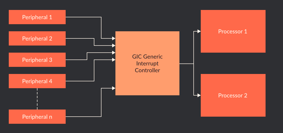
One of the main differences between the traditional Intel-based x86 architecture and ARM is ARM’s use of the Generic Interrupt Controller (GIC). The Advanced Programmable Interrupt Controller (APIC) is the controller most Windows engineers know — Intel’s family of interrupt controllers — because most Windows machines run on Intel.
The GIC, on ARM, has gone through several iterations. The Surface Pro on which this analysis was performed uses GICv3. ARM has since published documentation for GICv5, announced a few months ago. This section is just an introduction to the basics — the ARM documentation should be the curious reader’s next stop for lower-level detail.
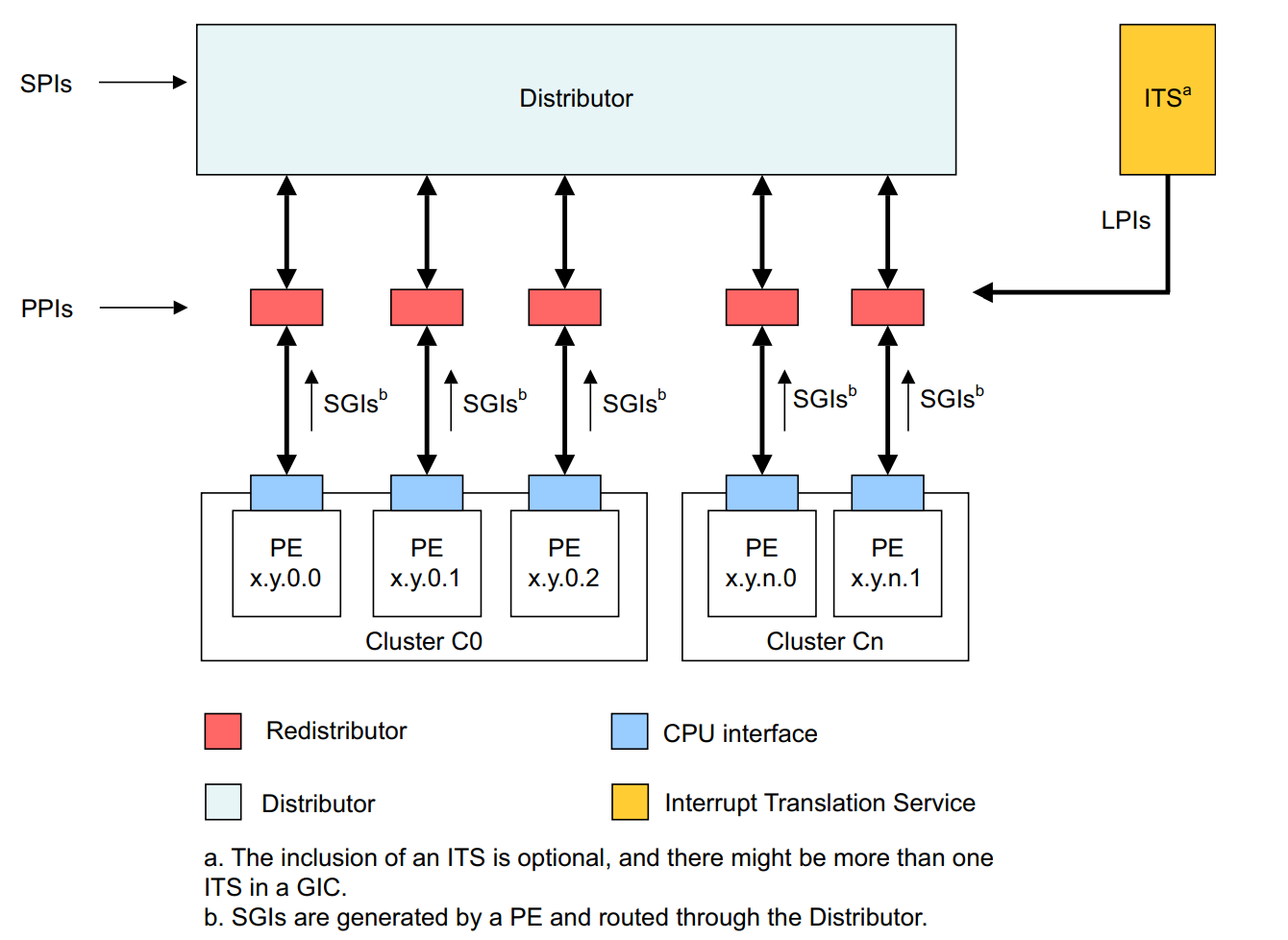
The main purpose of a GIC on an ARM system is to give software a standardized way to handle interrupts. The figure below, from ARM, provides a high-level overview of GIC interrupt delivery.
This section is not a glossary of GIC terminology — ARM provides documentation for the lower-level details. It is still worth calling out the following items, specifically as they exist in GICv3 (some of which are not necessarily new to GICv3):
There are two types of interrupts: IRQ and FIQ.
- IRQ is a standard interrupt request at normal priority.
- FIQ is a fast interrupt request which is higher priority than an IRQ.
There are four main “sources” of interrupts:
- External (Shared Peripheral Interrupt, SPI). External in the sense that the interrupt can be delivered to any processor.
- Internal (Private / Per-Processor Peripheral Interrupt, PPI). Private to a particular processor. A common example is a performance interrupt generated on a specific processor. The PMU is a per-CPU construct, and a target CPU can be configured to generate performance information that fires an interrupt when certain conditions are true — producing a PPI.
- Software-based (Software Generated Interrupt, SGI). The “ARM” version of an IPI — an inter-processor interrupt where one core sends an interrupt to another core.
- Locality-specific (Locality-specific Peripheral Interrupt, LPI). These are always message-based interrupts that can be generated from an Interrupt Translation Service (ITS).
Although Windows, as noted in an earlier post, doesn’t really use TrustZone with VBS enabled (VTLs provide non-secure / secure world functionality), interrupts are still divided into “secure” and “non-secure” categories tied to TrustZone security states.
A GIC also provides virtual interrupt functionality (vGIC) for hypervisors, with details that vary based on the GIC version — more on this later.
In addition to handling interrupts that fire from an “interrupt signal” generated by hardware (sometimes called hardware “buzzing” or “poking” the interrupt controller), GICs also support message-based interrupts. The delivery mechanism for these varies slightly — more on that later. Because each interrupt source is made up of multiple interrupt IDs (INTIDs) — for example, IDs 0–15 are SGIs, 16–31 are PPIs, etc. — not every single ID needs a physical wire.
Notice the recurring concept of interrupt sources — each represented by a particular INTID, mapped to an “interrupt line” within a particular “group” of sources (SPI, PPI, etc.). Interrupts arrive on these lines. Before getting to the Windows implementation, here is a quick summary of four important structures in the GIC architecture, collectively referred to as the Interrupt Routing Infrastructure (IRI). The IRI and interrupt-routing scheme, taken from the Arm Generic Interrupt Controller Architecture Specification, looks like this:
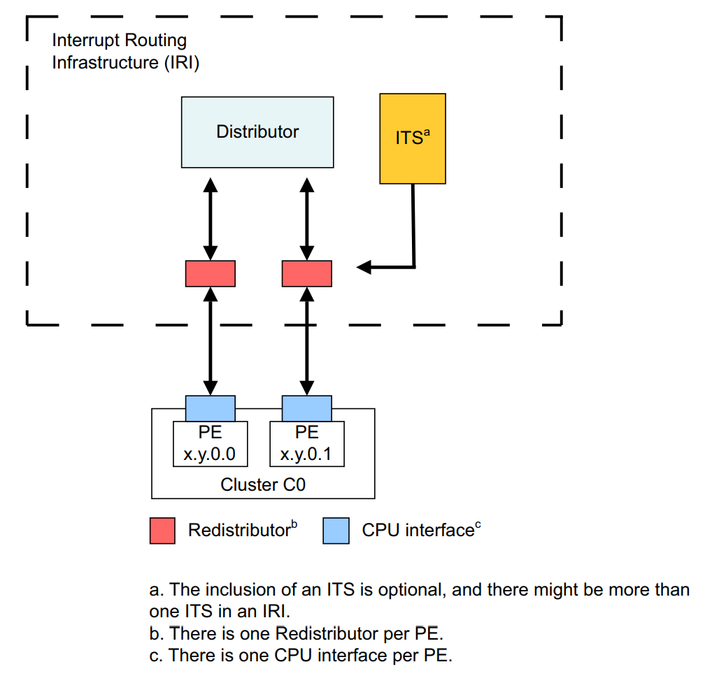
GIC Distributor
The GIC distributor is the “brain” of the interrupt schema, and all physical interrupt sources are wired to it. It is physically present on a particular SoC (system on a chip — how ARM integrates CPU, GPU, memory controllers, peripherals, etc., onto a single chip). It is always accessible via physical memory, not a system register, although the Windows kernel also maps it into virtual memory. There is a single distributor on a system.
The distributor primarily prioritizes and distributes physical interrupts to the redistributors (and CPU interfaces). This is especially true for SPIs, which are “external” to any particular CPU — the distributor must route the interrupt to the specific CPU that should handle it.
The distributor is involved in software-generated interrupts like IPIs (even though the interrupts originate from a particular processor) and facilitates routing. For interrupts that are local to a single CPU (like PPIs), the distributor does not need to be involved.
GIC Redistributor
Redistributors are per-CPU structures — there is only one redistributor per CPU. The redistributor receives SPIs that are routed from the interrupt source via the distributor. Redistributors have a few more “moving parts” and nuances.
When software-initiated interrupts (like an inter-processor interrupt requested from software) occur (SGIs), they are generated by both the issuing CPU’s interface and redistributor. From these components, the SGI is routed to the distributor and then on to the target CPU’s redistributor and CPU interface.
PPIs are local to a specific CPU, so the distributor is not involved at all — the source interrupt is routed directly to the CPU’s redistributor. LPIs are also routed to a target redistributor.
GIC CPU Interface
The various CPU interfaces are the mechanism through which a core actually receives an interrupt. There is both a physical CPU interface and a virtual CPU interface, but unless otherwise stated “CPU interface” here means the physical interface. The CPU interface is accessible through system registers (or a memory-mapped interface, but Windows uses system registers). This means the registers can be used to mask interrupts and control the interrupt state on the CPU.
GIC Interrupt Translation Services (ITS)
The ITS is optional in GICv3 (the version on the test machine). Its primary purpose is message-based interrupts (MSIs). When present, the ITS is responsible for routing LPIs (which represent message-based interrupts) to a target CPU’s redistributor, and for translating the MSI request into an LPI.
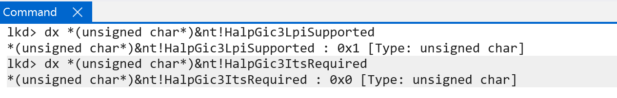
The Surface Pro on which this analysis was performed does implement an ITS. However, because the OS is virtualized, Hyper-V does not expose it to the root partition (credit to Longhorn for pointing this out). GICv4 requires an ITS because it must support virtual LPIs — GICv4 supports direct injection of virtual interrupts into a VM without involving the hypervisor.
The figure below summarizes the basic interrupt routing schema — again from ARM documentation.
Windows on ARM Interrupt Initialization and Discovery
Although there are some references to interrupt functionality before it, the natural entry point is nt!HalpInitializeInterrupts. This function handles most of the interrupt discovery and initialization that matters here. It takes a single parameter — the loader parameter block from the bootloader, represented by the nt!_LOADER_PARAMETER_BLOCK structure.
One of the first things this function does is perform GIC discovery. The kernel attempts to discover GICv3 first, and defaults to checking whether GICv1 is available.
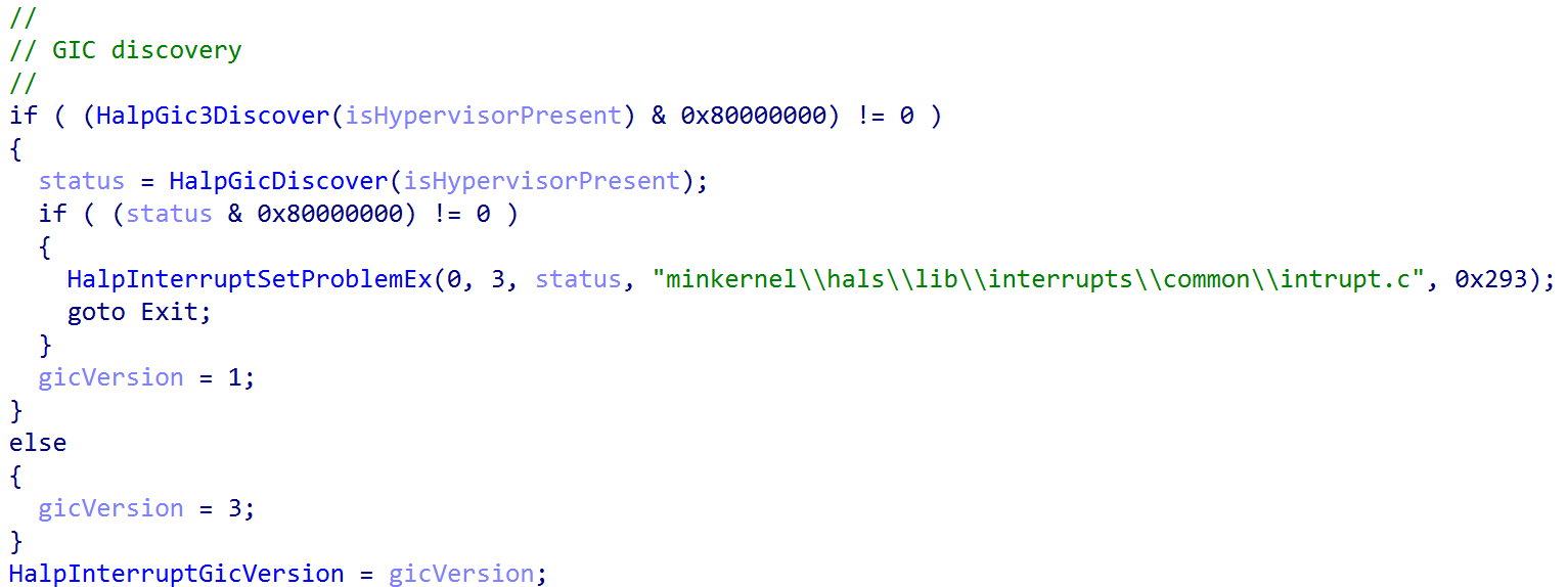
nt!HalpInitializeInterrupts. Source: original article.As a point of contention,
nt!HalSetInterruptProblemtakes a parameter from theINTERRUPT_PROBLEMenum. For ARM devices, the following values are valid — useful for debugging and determining what is occurring. In this case the error from the image above shows that discovery is occurring (InterruptProblemFailedDiscovery):
lkd> dt nt!_INTERRUPT_PROBLEM
   InterruptProblemNone = 0n0
   InterruptProblemMadtParsingFailure = 0n1
   InterruptProblemNoControllersFound = 0n2
   InterruptProblemFailedDiscovery = 0n3
   InterruptProblemInitializeLocalUnitFailed = 0n4
   InterruptProblemInitializeIoUnitFailed = 0n5
   InterruptProblemSetLogicalIdFailed = 0n6
   InterruptProblemSetLineStateFailed = 0n7
   InterruptProblemGenerateMessageFailed = 0n8
   InterruptProblemConvertIdFailed = 0n9
   InterruptProblemCmciSetupFailed = 0n10
   InterruptProblemQueryMaxProcessorsCalledTooEarly = 0n11
   InterruptProblemProcessorReset = 0n12
   InterruptProblemStartProcessorFailed = 0n13
   InterruptProblemProcessorNotAlive = 0n14
   InterruptProblemLowerIrqlViolation = 0n15
   InterruptProblemInvalidIrql = 0n16
   InterruptProblemNoSuchController = 0n17
   InterruptProblemNoSuchLines = 0n18
   InterruptProblemBadConnectionData = 0n19
   InterruptProblemBadRoutingData = 0n20
   InterruptProblemInvalidProcessor = 0n21
   InterruptProblemFailedToAttainTarget = 0n22
   InterruptProblemUnsupportedWiringConfiguration = 0n23
   InterruptProblemSpareAlreadyStarted = 0n24
   InterruptProblemClusterNotFullyReplaced = 0n25
   InterruptProblemNewClusterAlreadyActive = 0n26
   InterruptProblemNewClusterTooLarge = 0n27
   InterruptProblemCannotHardwareQuiesce = 0n28
   InterruptProblemIpiDestinationUpdateFailed = 0n29
   InterruptProblemNoMemory = 0n30
   InterruptProblemNoIrtEntries = 0n31
   InterruptProblemConnectionDataBaitAndSwitch = 0n32
   InterruptProblemInvalidLogicalFlatId = 0n33
   InterruptProblemDeinitializeLocalUnitFailed = 0n34
   InterruptProblemDeinitializeIoUnitFailed = 0n35
   InterruptProblemMismatchedThermalLvtIsr = 0n36
   InterruptProblemHvRetargetFailed = 0n37
   InterruptProblemDeferredErrorSetupFailed = 0n38
   InterruptProblemBadInterruptPartition = 0n39
nt!HalpGic3Discover begins by enumerating the Advanced Configuration and Power Interface (ACPI) table named “APIC”. To minimise work for the Hardware Abstraction Layer (HAL), Windows effectively requires ARM64 systems running Windows to support ACPI.
ACPI is a specification used to let hardware describe the interfaces software can use. It is especially relevant here because it describes interrupt functionality on the system. Interrupts are not just a software construct — chips have physical wiring used for many interrupt operations — so ACPI tables describe the actual hardware configuration of the machine, including the interrupt configuration, to the OS.
The ACPI “APIC” table really refers to the Multiple APIC Description Table (MADT). Although the name says APIC, because Intel-based systems have dominated for so long, the latest ACPI versions (5.0 and beyond) have added descriptors for GIC — which is what ARM-based systems use. The MADT, as it is referred to here, describes the interrupt functionality of the system — specifically the GIC and the GIC distributor previously mentioned.
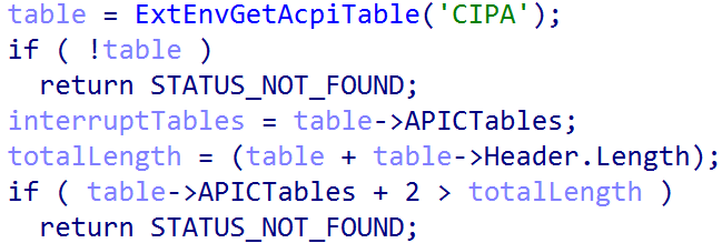
nt!ExtEnvGetAcpiTable. Source: original article.nt!ExtEnvGetAcpiTable returns a pointer to an nt!_MAPIC structure, which represents the MADT and has the following layout. This can be cross-referenced with the latest ACPI specification from UEFI:
kd> dt nt!_MAPIC -r2
   +0x000 Header           : _DESCRIPTION_HEADER
      +0x000 Signature        : Uint4B
      +0x004 Length           : Uint4B
      +0x008 Revision         : UChar
      +0x009 Checksum         : UChar
      +0x00a OEMID            : [6] Char
      +0x010 OEMTableID       : [8] Char
      +0x018 OEMRevision      : Uint4B
      +0x01c CreatorID        : [4] Char
      +0x020 CreatorRev       : Uint4B
   +0x024 LocalAPICAddress : Uint4B
   +0x028 Flags            : Uint4B
   +0x02c APICTables       : [1] Uint4B
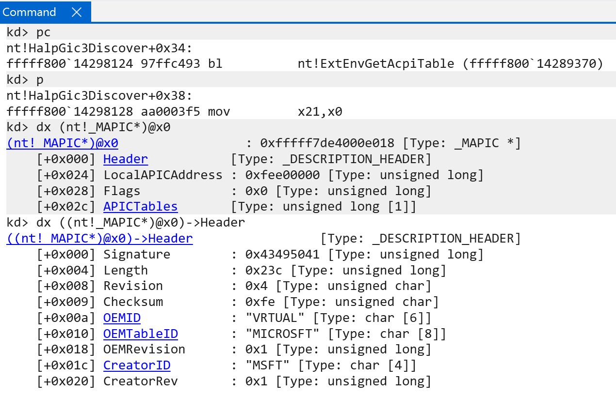
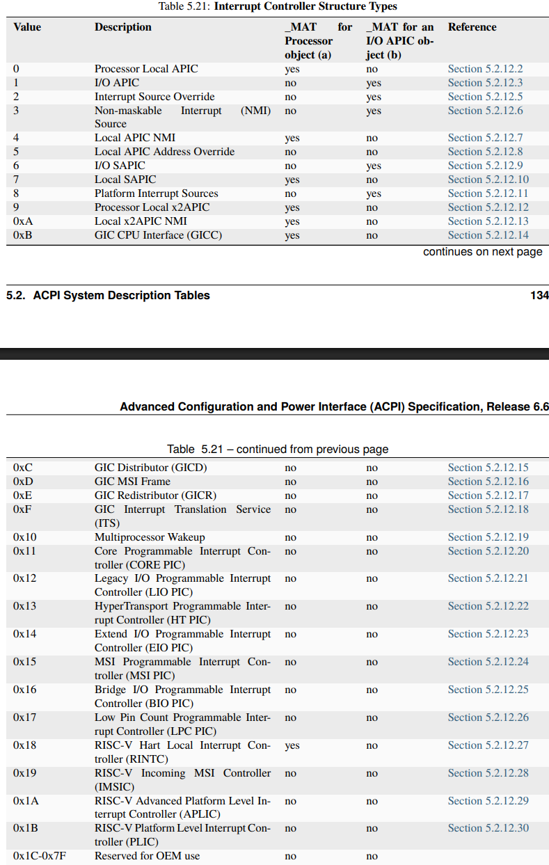
APICTables member of nt!_MAPIC. Source: original article.The APICTables member of this structure corresponds to Interrupt Controller Structure[n] in the official ACPI specification — a list of interrupt controller structures available on the system.
The nt!_MAPIC structure acts as a header describing the various interrupt structures that follow — together they make up the interrupt functionality of the system. WinDbg provides a useful extension that parses what is present:
kd> !mapic @x0
MAPIC - HEADER - fffff7de4000e018
  Signature:               APIC
  Length:                  0x0000023c
  Revision:                0x04
  Checksum:                0xfe
  OEMID:                   VRTUAL
  OEMTableID:              MICROSFT
  OEMRevision:             0x00000001
  CreatorID:               MSFT
  CreatorRev:              0x00000001
MAPIC - BODY - fffff7de4000e03c
  Local APIC Address:      0xfee00000
  Flags:                   00000000
  GIC Distributor
    Reserved1:             0x0000
    Identifier:            0x00000000
    Controller Addr:       0x00000000ffff0000
    GSIV Base:             0x00000000
    Reserved2:             0x00000000
    Version:               0x00000003
  Processor Local GIC
    Reserved:              0x0000
    Identifier:            0x00000000
    ACPI Processor ID:     0x00000001
    Flags:                 0x00000001
    Parking Proto Version: 0x00000000
    Perf Interrupt GSI:    0x00000017
    Parked Addr:           0x0000000000000000
    Controller Addr:       0x0000000000000000
    GICV:                  0x0000000000000000
    GICH:                  0x0000000000000000
    VGIC Maintenance Intr: 0x00000000
    GICR Base Addr:        0x00000000effee000
    MPIDR:                 0x0000000000000000
   PowerEfficiencyClass:   0x00
   SPE overflow interrupt GSI (PMBIRQ):   0x00
      Processor is Enabled
  Processor Local GIC
    Reserved:              0x0000
    Identifier:            0x00000000
    ACPI Processor ID:     0x00000002
    Flags:                 0x00000001
    Parking Proto Version: 0x00000000
    Perf Interrupt GSI:    0x00000017
    Parked Addr:           0x0000000000000000
    Controller Addr:       0x0000000000000000
    GICV:                  0x0000000000000000
    GICH:                  0x0000000000000000
    VGIC Maintenance Intr: 0x00000000
    GICR Base Addr:        0x00000000f000e000
    MPIDR:                 0x0000000000000001
   PowerEfficiencyClass:   0x00
   SPE overflow interrupt GSI (PMBIRQ):   0x00
      Processor is Enabled
  Processor Local GIC
    Reserved:              0x0000
    Identifier:            0x00000000
    ACPI Processor ID:     0x00000003
    Flags:                 0x00000001
    Parking Proto Version: 0x00000000
    Perf Interrupt GSI:    0x00000017
    Parked Addr:           0x0000000000000000
    Controller Addr:       0x0000000000000000
    GICV:                  0x0000000000000000
    GICH:                  0x0000000000000000
    VGIC Maintenance Intr: 0x00000000
    GICR Base Addr:        0x00000000f002e000
    MPIDR:                 0x0000000000000002
   PowerEfficiencyClass:   0x00
   SPE overflow interrupt GSI (PMBIRQ):   0x00
      Processor is Enabled
  Processor Local GIC
    Reserved:              0x0000
    Identifier:            0x00000000
    ACPI Processor ID:     0x00000004
    Flags:                 0x00000001
    Parking Proto Version: 0x00000000
    Perf Interrupt GSI:    0x00000017
    Parked Addr:           0x0000000000000000
    Controller Addr:       0x0000000000000000
    GICV:                  0x0000000000000000
    GICH:                  0x0000000000000000
    VGIC Maintenance Intr: 0x00000000
    GICR Base Addr:        0x00000000f004e000
    MPIDR:                 0x0000000000000003
   PowerEfficiencyClass:   0x00
   SPE overflow interrupt GSI (PMBIRQ):   0x00
      Processor is Enabled
  Processor Local GIC
    Reserved:              0x0000
    Identifier:            0x00000000
    ACPI Processor ID:     0x00000005
    Flags:                 0x00000001
    Parking Proto Version: 0x00000000
    Perf Interrupt GSI:    0x00000017
    Parked Addr:           0x0000000000000000
    Controller Addr:       0x0000000000000000
    GICV:                  0x0000000000000000
    GICH:                  0x0000000000000000
    VGIC Maintenance Intr: 0x00000000
    GICR Base Addr:        0x00000000f006e000
    MPIDR:                 0x0000000000000004
   PowerEfficiencyClass:   0x00
   SPE overflow interrupt GSI (PMBIRQ):   0x00
      Processor is Enabled
  Processor Local GIC
    Reserved:              0x0000
    Identifier:            0x00000000
    ACPI Processor ID:     0x00000006
    Flags:                 0x00000001
    Parking Proto Version: 0x00000000
    Perf Interrupt GSI:    0x00000017
    Parked Addr:           0x0000000000000000
    Controller Addr:       0x0000000000000000
    GICV:                  0x0000000000000000
    GICH:                  0x0000000000000000
    VGIC Maintenance Intr: 0x00000000
    GICR Base Addr:        0x00000000f008e000
    MPIDR:                 0x0000000000000005
   PowerEfficiencyClass:   0x00
   SPE overflow interrupt GSI (PMBIRQ):   0x00
      Processor is Enabled
  MSI Frame
    Reserved1:             0x0000
    Identifier:            0x00000001
    Physical Address:      0x00000000effe8000
    Flags:                 0x00000001
    SpiCount:              0x0024
    SpiBase:               0x039d
End of MAPIC.
Several structures are present here: the GIC distributor (of which there can only be one), the “Processor Local GIC” entries referring to the per-CPU “interfaces” mentioned earlier, per-CPU GIC redistributors (GIC Redistributor / GICR Structure), and a single MSI (GIC MSI Frame Structure) interface. The test machine has 6 CPUs / 12 cores, which matches the six GICC entries.
nt!HalpGic3Discover is then responsible for parsing all of the interrupt structures present and informing the kernel about which GIC features are supported (LPIs supported, Interrupt Translation Services required, how many GIC CPU interfaces are enabled, etc.). It takes a single parameter — a value from the EXT_ENV enum that describes more about the current operating environment — which is passed down the initialization stack. Here, for instance, the operating environment is ExtEnvHvRoot, because VBS is enabled and the Windows OS lives in the root partition, so the GIC needs to interact with the root partition. As shown later (especially for virtual interrupts), knowing the execution environment matters.
lkd> dt nt!_EXT_ENV
   ExtEnvUnknown = 0n0
   ExtEnvNativeHal = 0n1
   ExtEnvHvRoot = 0n2
   ExtEnvHvGuest = 0n3
   ExtEnvHypervisor = 0n4
   ExtEnvSecureKernel = 0n5
As a point of contention, however, dynamic analysis is done in a VM, so — obviously — the operating environment is that of a guest:
0: kd> dx ((nt!_GIC3_DATA*)0xfffff7f440000a10)->ExtEnv
((nt!_GIC3_DATA*)0xfffff7f440000a10)->ExtEnv : ExtEnvHvGuest (3) [Type: _EXT_ENV]
On success, the GIC distributor is validated via nt!Gic3ValidateIoUnit. As noted, the single GIC distributor is where all interrupt sources are wired — a very important structure. On Windows, the nt!_GIC_DISTRIBUTOR structure represents it.
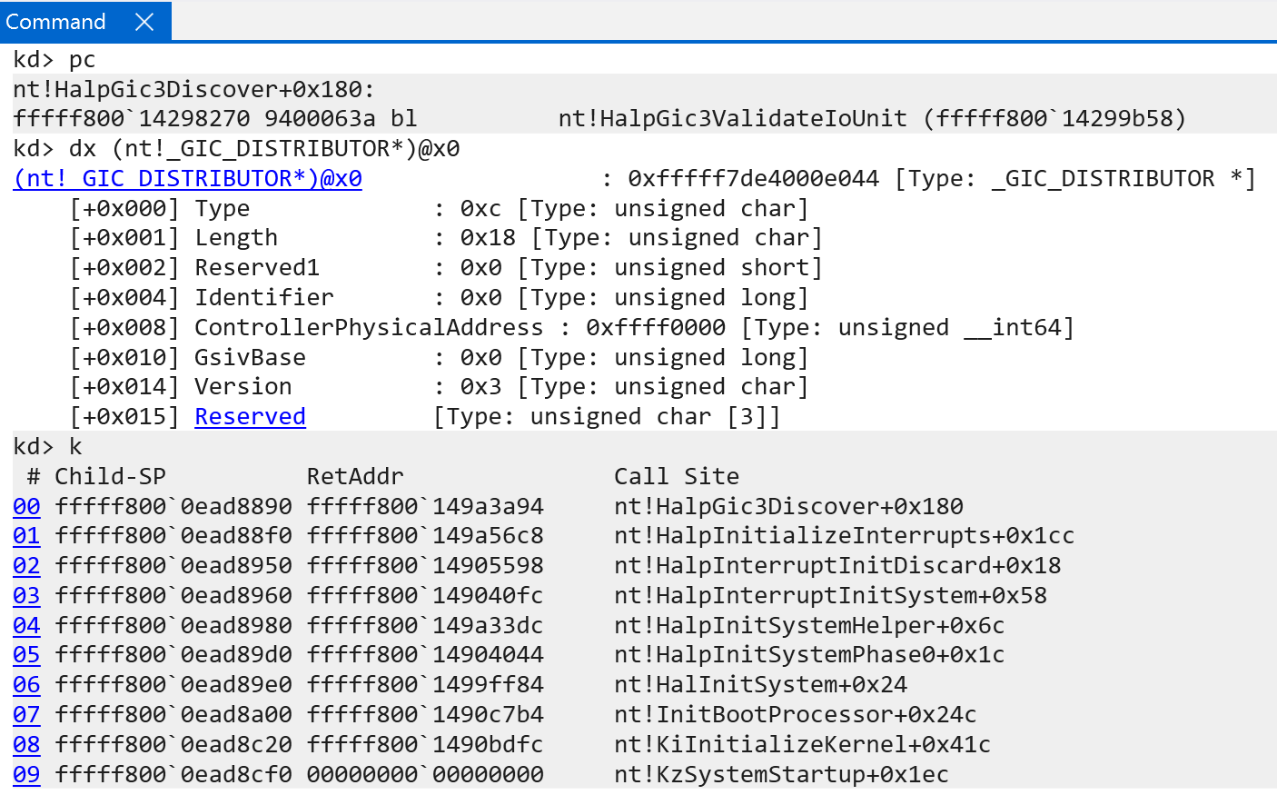
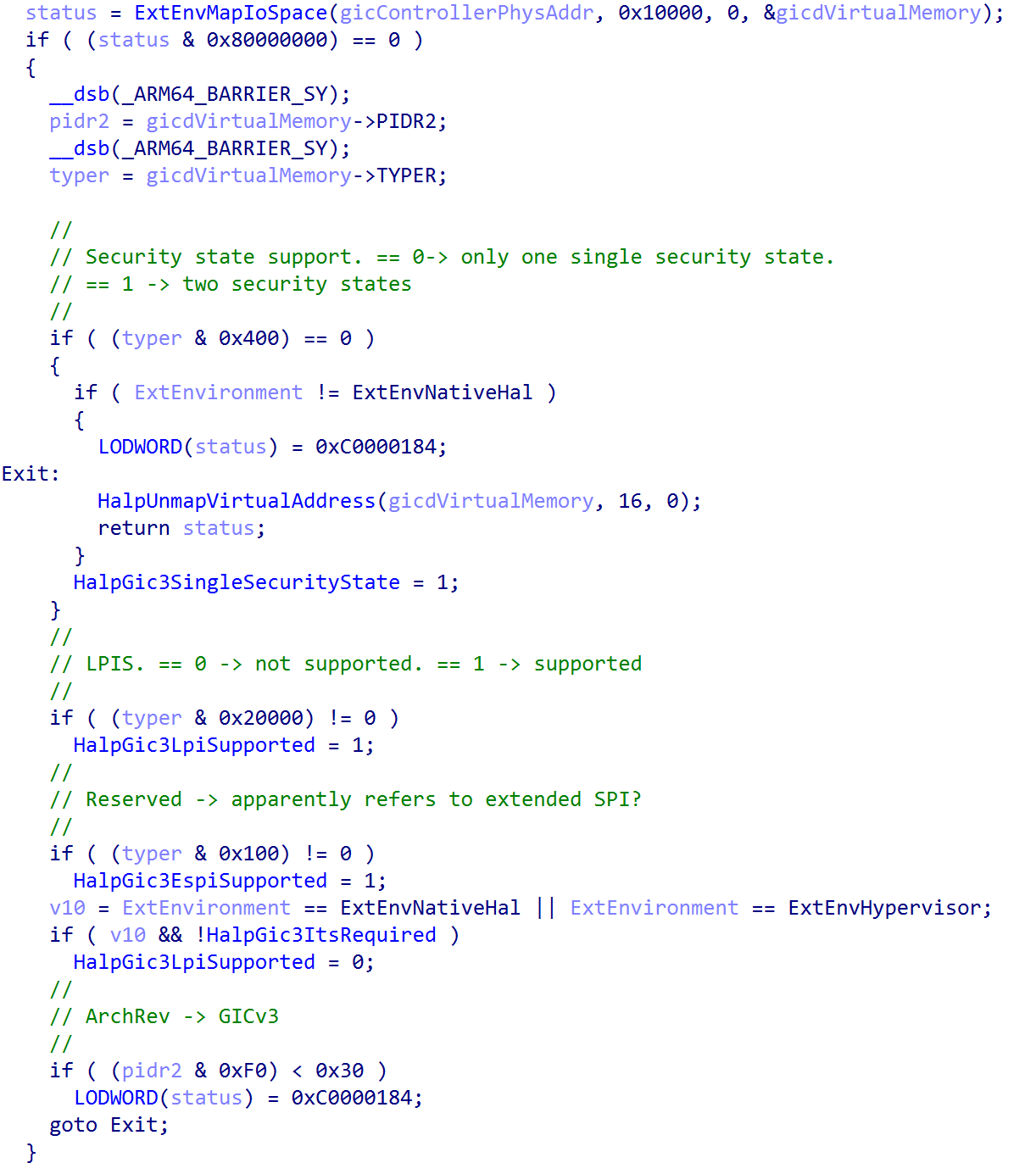
nt!_GIC_DISTRIBUTOR structure. Source: original article.The Windows-defined structure describes the GIC distributor, but the distributor itself is mapped into physical memory and accessed on Windows via the ControllerPhysicalAddress member of nt!_GIC_DISTRIBUTOR. That address has the layout of the GIC distributor described by ARM. The structure (which is not in the Windows symbols — it was manually added into IDA) fills out the remaining “enlightened” data of the kernel, including the number of supported security states, whether LPIs are supported (supported, not in use), extended SPI support, and a last GIC version check.
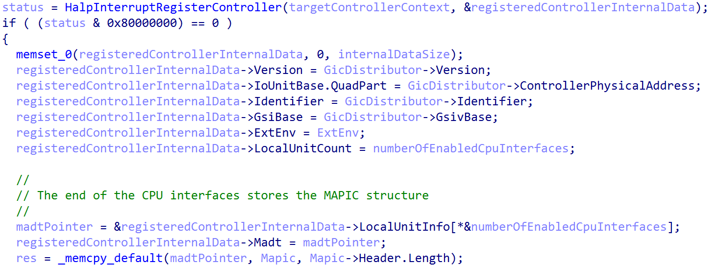
After the GIC is validated, the interrupt controller is registered with Windows via nt!HalpGic3RegisterIoUnit. This function fills in the information used to build the list of registered interrupt controllers on the system. On the test machine, only one controller is registered. The function fills out an nt!_REGISTERED_INTERRUPT_CONTROLLER structure, adds it to the doubly-linked list managed by nt!HalpRegisteredInterruptControllers, and increments nt!HalpInterruptControllerCount. WinDbg can parse the entire linked list (only one link in this case) to view the registered interrupt controller.
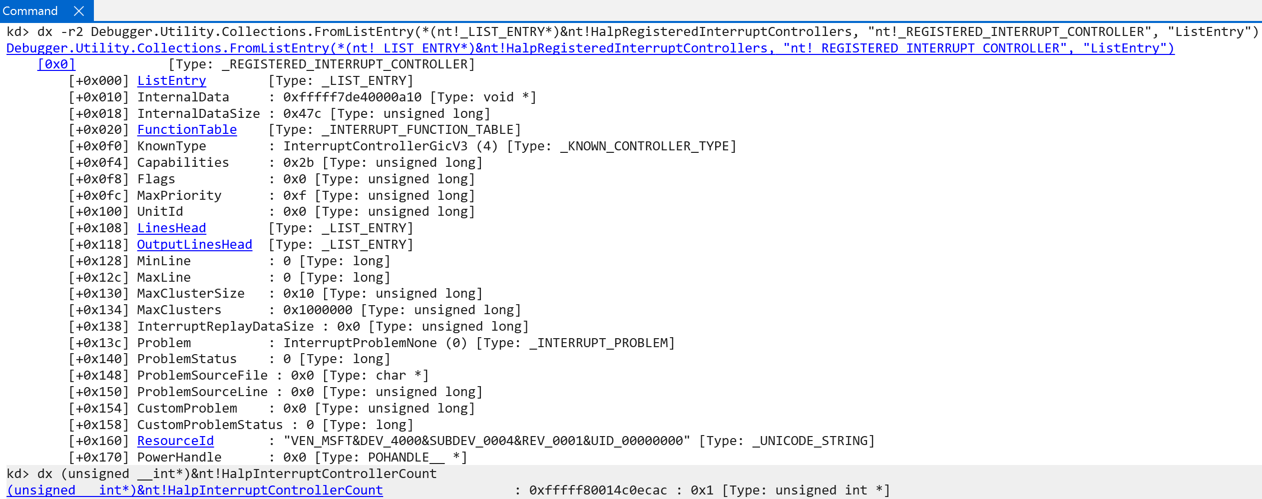
nt!HalpRegisteredInterruptControllers. Source: original article.The KnownType is set to InterruptControllerGicV3 — which is what we expect. This is how Windows goes from interrupt functionality discovery to actually registering an interrupt controller with the OS from what hardware exposes. The registered interrupt controller also carries a list of functions (in the nt!_INTERRUPT_FUNCTION_TABLE structure) used to further configure the interrupt controller and / or for the HAL to interact with it. These are not interrupt-handler functions.
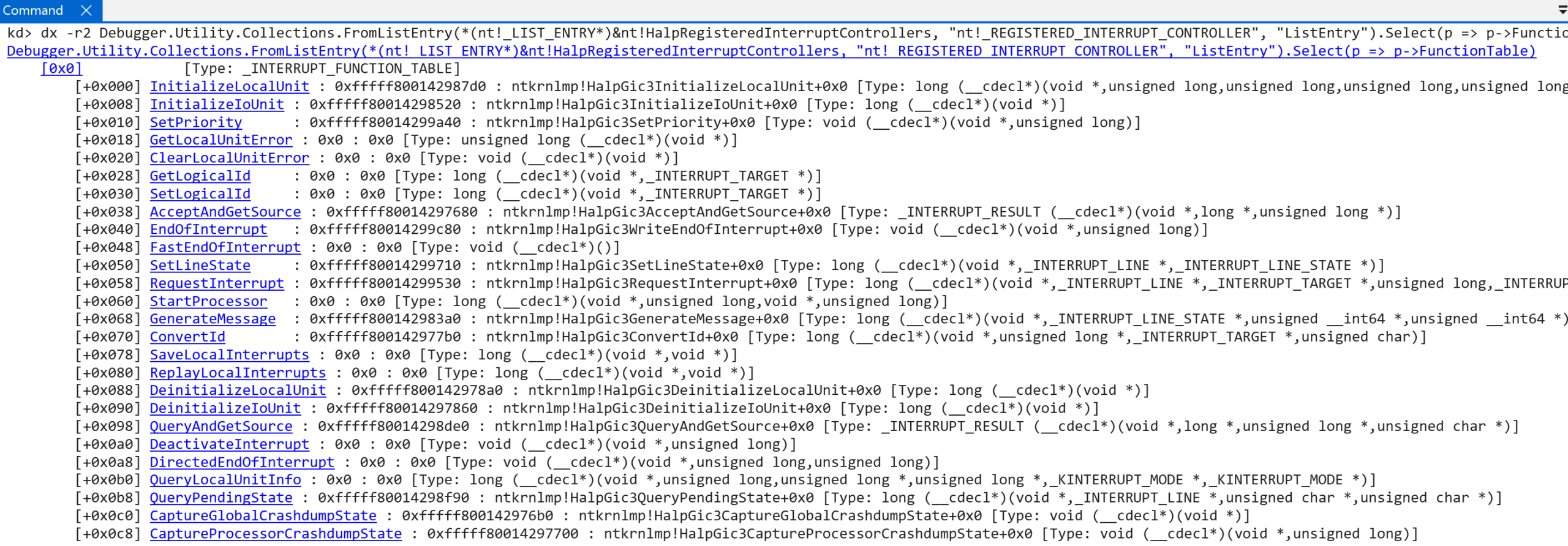
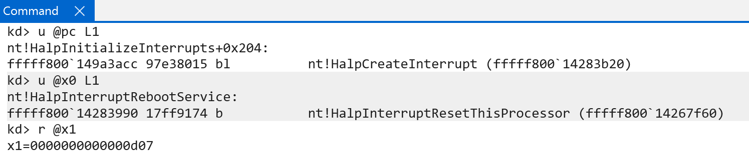
nt!_INTERRUPT_FUNCTION_TABLE. Source: original article.After registration, the controller is still not fully initialized. First, the GIC version is preserved (nt!HalpInterruptGicVersion). Next, before each interrupt controller is fully initialized (in this case just one), many of the crucial and low-level interrupt handlers — the CPU’s SGI (i.e., inter-processor interrupt, via KiIpiServiceRoutine), the reboot service (nt!HalpInterruptRebootService), etc. — are registered via nt!HalpCreateInterrupt. That function allocates an interrupt object (nt!_KINTERRUPT) representing a particular interrupt type and lets the OS / software register a particular interrupt service routine (KINTERRUPT->ServiceRoutine). nt!KeInitializeInterruptEx fills out most of the nt!_KINTERRUPT object, including the parameters passed from nt!HalpCreateInterrupt such as the ServiceRoutine, Vector (more on this shortly — the maximum value is 0xFFF), and Irql (the IRQL at which the CPU will run when the interrupt occurs).
KINTERRUPT object initialization. Source: original article.After the various interrupt objects are created (and before nt!HalpInterruptInitializeController runs), they are connected to the IDT via nt!KiConnectInterruptInternal.
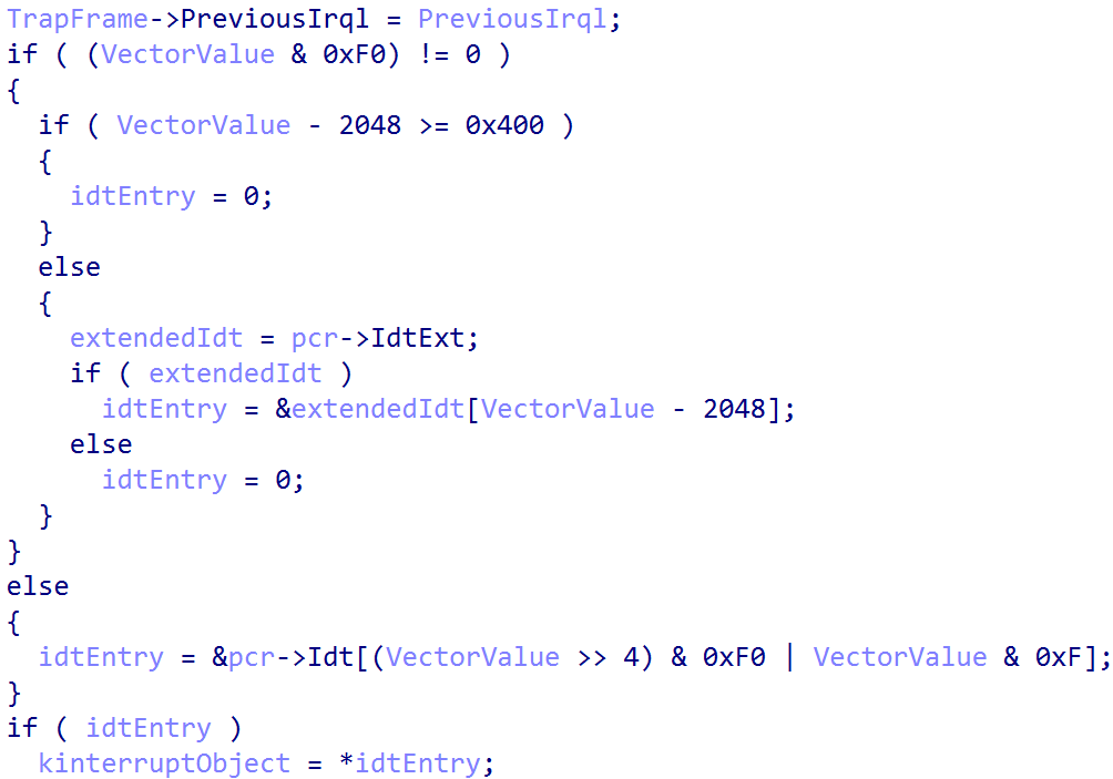
The first thing nt!KiConnectInterruptInternal (on Windows on ARM) does is some basic validation. The target interrupt’s vector number cannot exceed 4095 (more on this later), the IRQL associated with the interrupt cannot be higher than HIGH_LEVEL, the Number member of the KINTERRUPT object must be valid (this is not the interrupt number but the target CPU number for which the interrupt has been initialized), and the SynchronizationIrql associated with the interrupt object (the IRQL at which the lock stored in the interrupt object itself is acquired) must be valid.
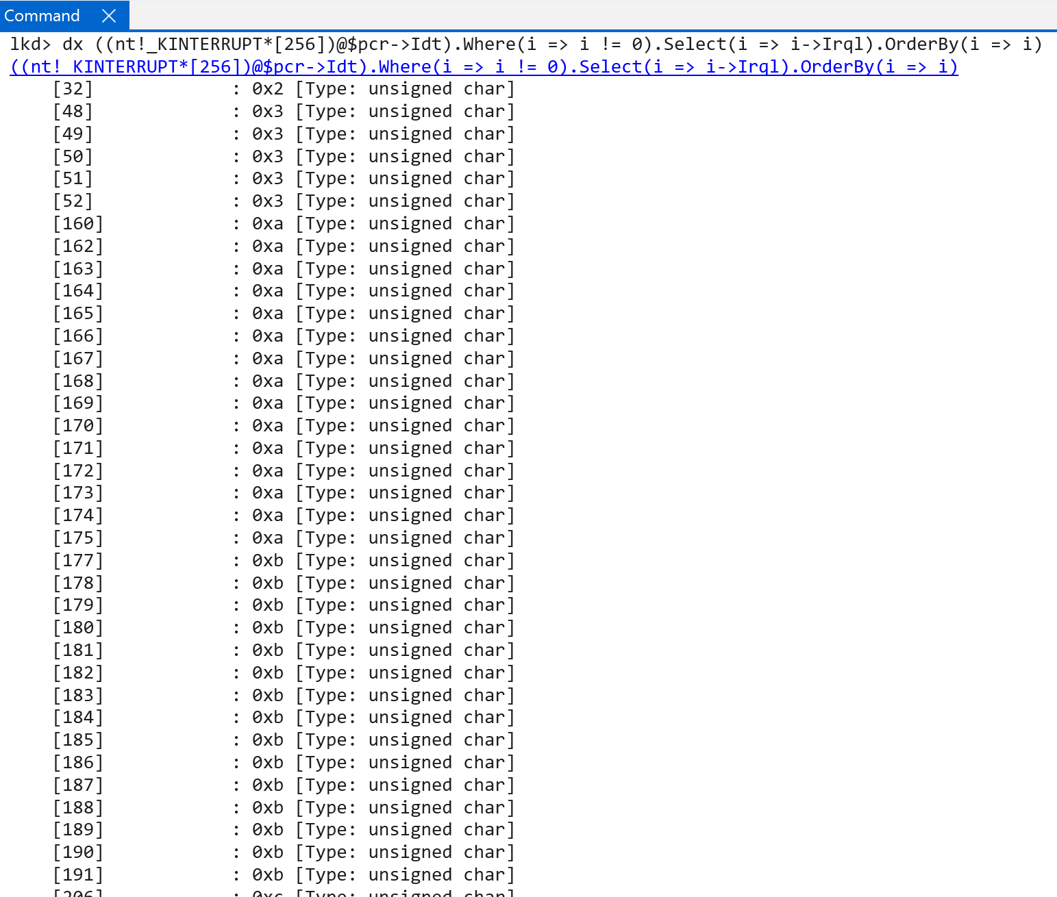
After basic validation, the kernel indexes the per-CPU IDT via KPCR->Idt (using nt!KiGetIdtEntry) to locate the target slot where the interrupt object to be connected will reside. Note this uses KPCR->Idt, not KPCR->IdtBase, which is the corresponding field on x64 and does not exist on ARM64. This slot stores the first 16 registered interrupts; anything beyond that lives in the extended IDT (KPCR->IdtExt).
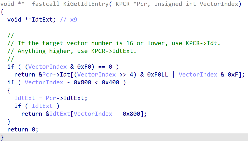
nt!KiGetIdtEntry indexes KPCR->Idt. Source: original article.For example, the SGI / IPI interrupt is registered with a call to nt!HalpCreateInterrupt with the following parameters:
HalpCreateInterrupt(KiIpiServiceRoutine,
                    0xE01,
                    0xE);
0xE01 is the KINTERRUPT.Vector value, as shown below.
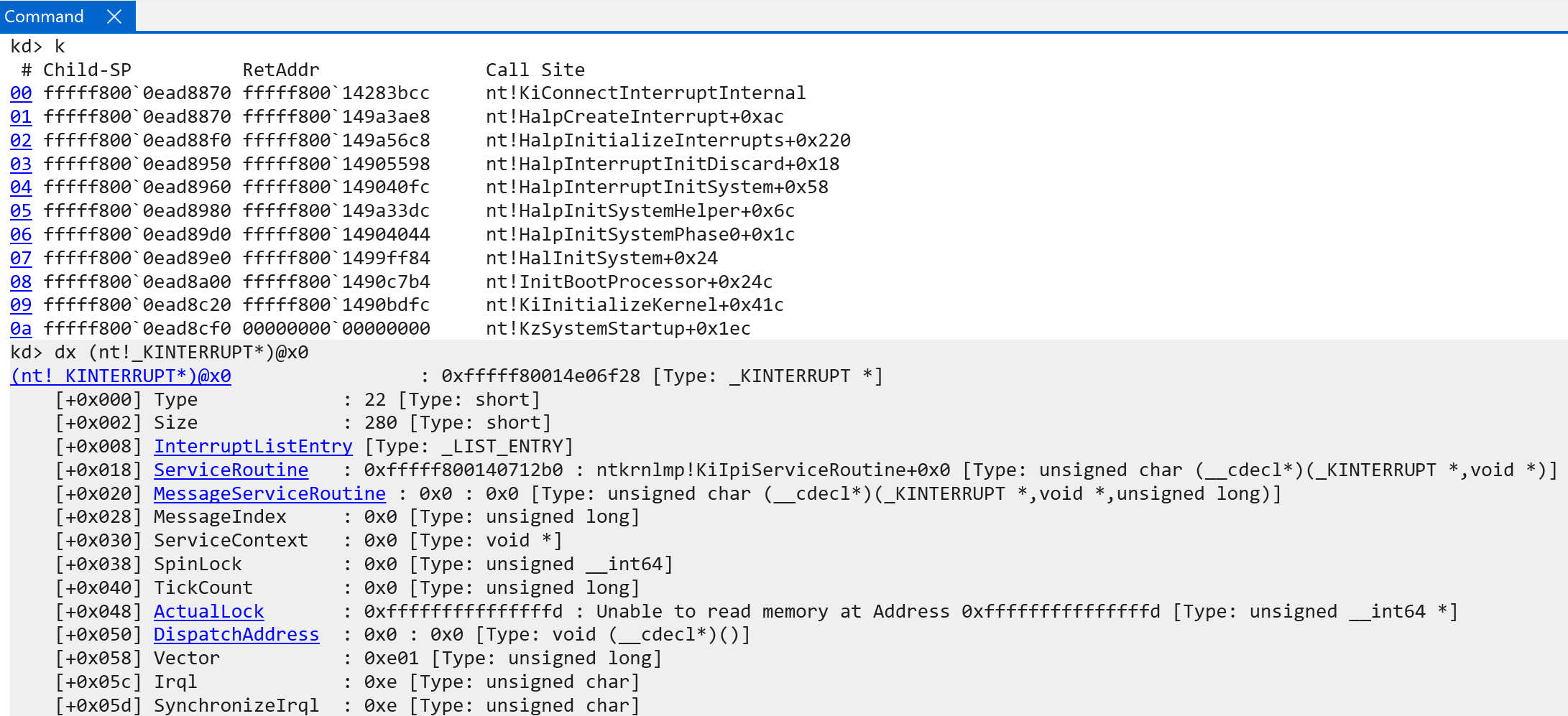
So nt!KiGetIdtEntry here indexes the first “regular” IDT (KPCR->Idt), because the lower nibble is less than the maximum value of 16. There is a difference in how IDT entries are accessed between x64 and ARM64 (the CPU does not learn about the IDT layout via the IDTR, for example, because a generic interrupt controller is being used). Even though the local variable is named VectorIndex, it is not strictly just an index — it contains more. This is visible in how the value is consumed in software:
- Extract the upper byte of
KINTERRUPT.Vector(0xE0). - Add the lower nibble to the remaining value.
In this example, 0xE01 becomes 0xE1. This is the index into the IDT for the target interrupt — the location where the actual interrupt object is written.
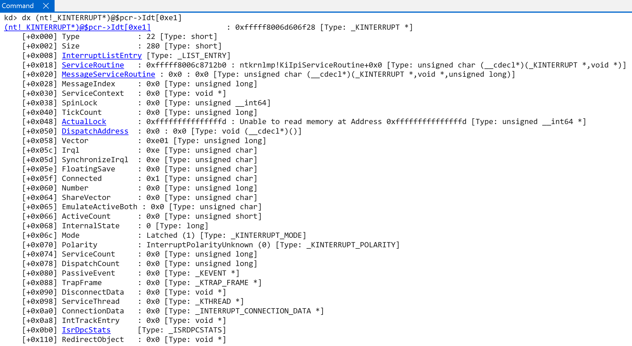
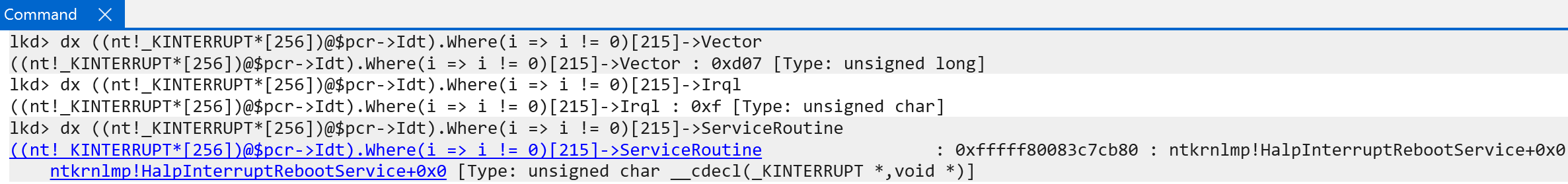
KINTERRUPT object into the IDT. Source: original article.As an aside, the vector value is effectively a masking of the target IRQL for the interrupt and the actual index into the IDT. So 0xE01 has an IRQL of 0xE, etc. — with one exception (the reason for which I do not currently understand): the interrupt associated with rebooting. That interrupt object (nt!HalpInterruptRebootService) has a vector of 0xd07 and an actual IRQL of 0x7.
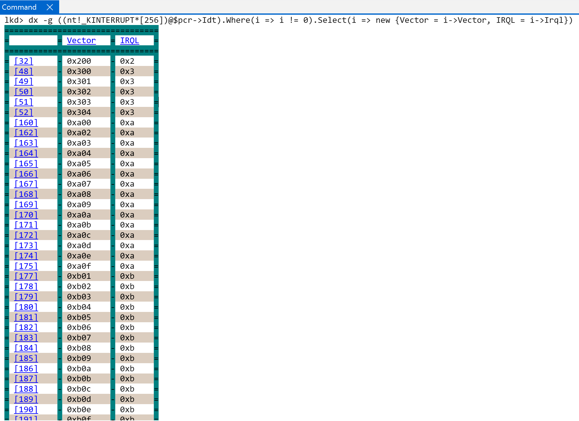
It would seem that in this scheme there can be 16 IRQLs (as on Windows on ARM), and each IRQL can have up to 16 associated interrupts — 256 in total. This is consistent with the IDT array in the processor control region (nt!_KPCR) being a hardcoded 256-element array.
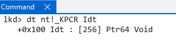
KPCR IDT array definition. Source: original article.As an aside, on the test ARM machine the lowest IRQL with a registered interrupt is 0x2 — DISPATCH_LEVEL. The service routine for this interrupt is nt!HalpInterruptSwServiceRoutine, which seems to indicate this is the software interrupt service routine (a wrapper around the real function, nt!KiSwInterruptDispatch — famous for being associated with PatchGuard and also present in the x64 IDT). It does not appear to be an actual interrupt handler — more of a “security-by-obscurity” feature.
nt!HalpInterruptSwServiceRoutine. Source: original article.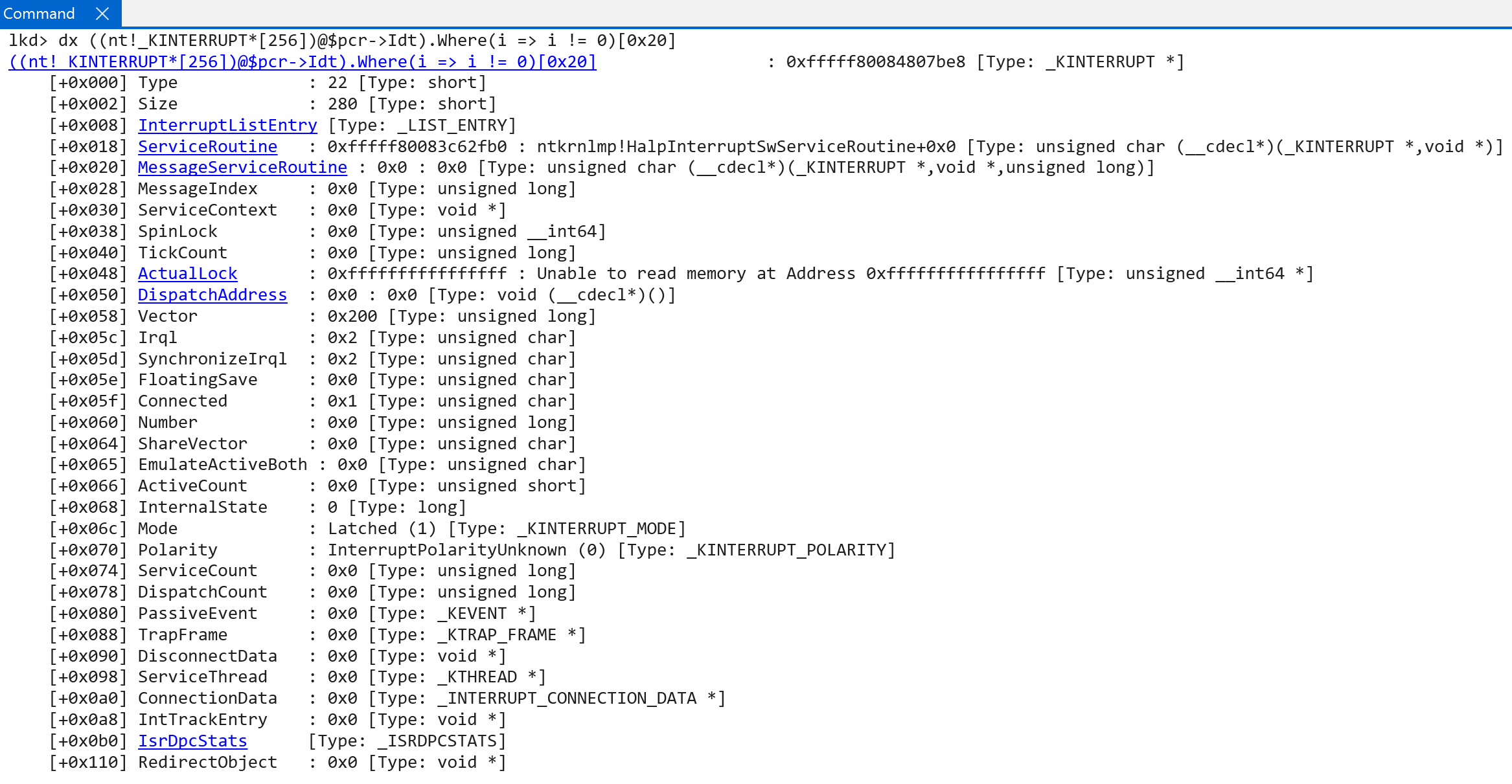
nt!KiSwInterruptDispatch. Source: original article.Once the initial interrupt objects have been connected to the software representation of the interrupt controller (nt!HalpRegisteredInterruptControllers), a call to nt!HalpInterruptInitializeController follows — performing most of the lower-level interrupt initialization logic. It begins by forwarding the in-scope registered interrupt controller to nt!HalpInterruptInitializeLocalUnit.
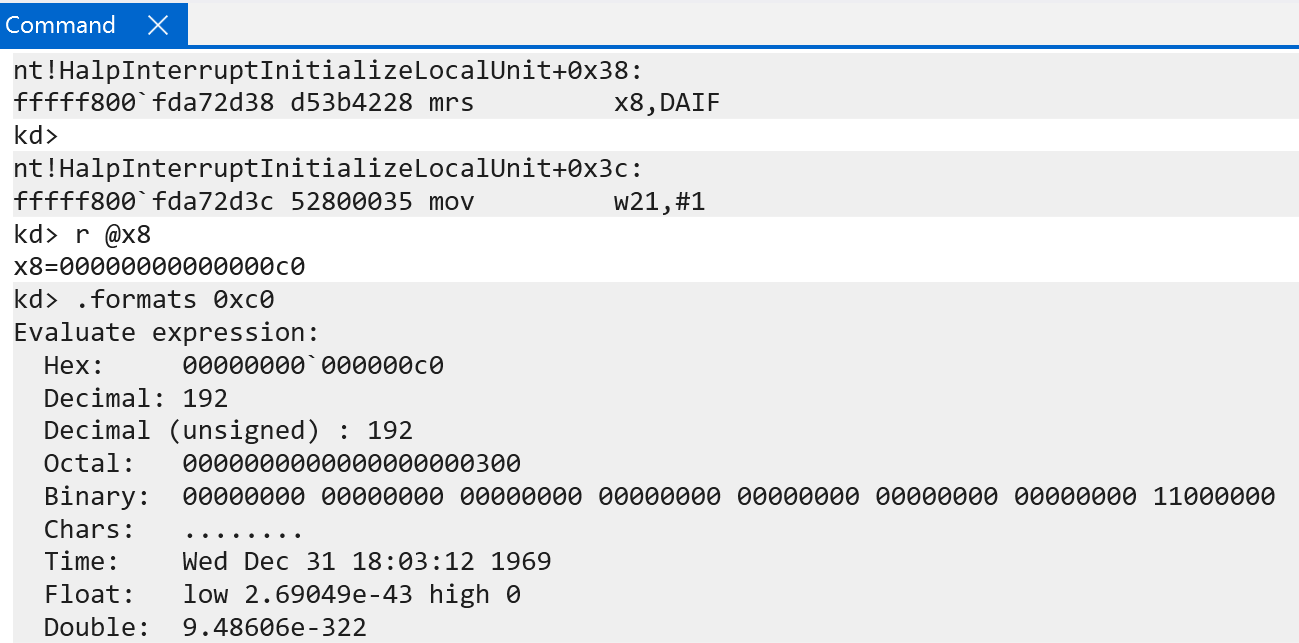
nt!HalpInterruptInitializeLocalUnit begins by checking whether the DAIF system register has DAIF.I set — an indication of whether IRQ exceptions are masked. This is another way of checking whether interrupts will be received by the current exception level. On the test machine, at this stage in system initialization, both FIQs and IRQs are masked. If for whatever reason they were not, this function would set DAIFSet to a mask of 0b11 — which allows writing to the DAIF system register.
After interrupts are temporarily disabled, nt!HalpInterruptInitializeLocalUnit invokes nt!HalpGic3InitializeLocalUnit — one of the functions registered with the interrupt controller (REGISTERED_INTERRUPT_CONTROLLER.FunctionTable[InitializeLocalUnit]). It receives an argument pointing to the registered controller’s internal data (REGISTERED_INTERRUPT_CONTROLLER.InternalData). The internal data is filled out in nt!HalpGic3RegisterIoUnit; after construction, it is stored in the global variable nt!HalpGic3. The internal data is exposed as a GIC3_DATA structure (in the symbols). Using an ANYSIZE_ARRAY pattern, the internal data is followed by N GIC3_LOCALUNIT_INFO structures, where N is the number of CPUs on the current machine.
GIC3_DATA structure. Source: original article.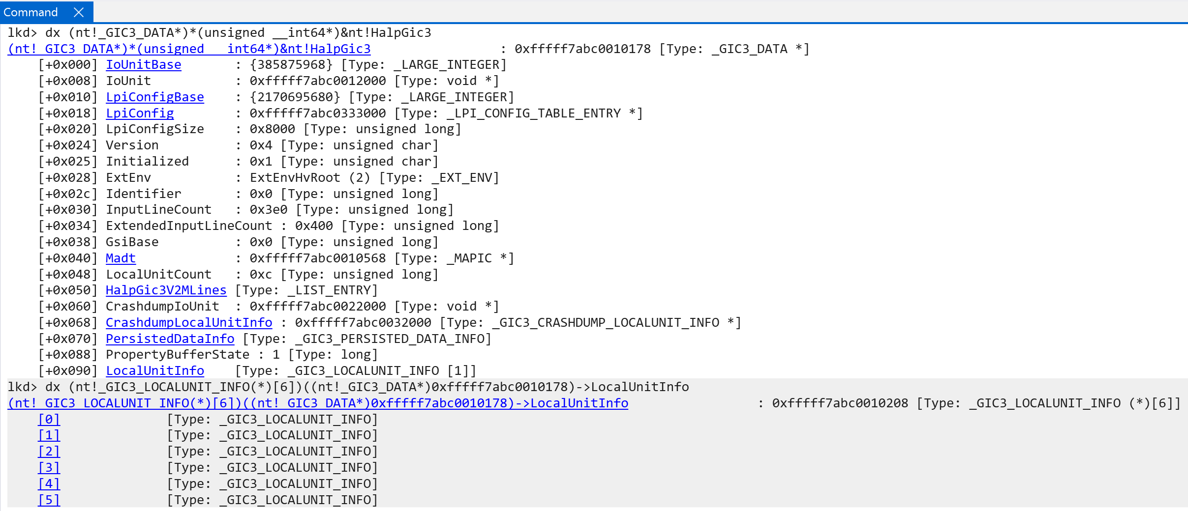
GIC3_LOCALUNIT_INFO structures. Source: original article.Some items of interest in the GIC3_DATA structure that add an extra layer of abstraction (most other data is self-explanatory):
IoUnitBase— the physical address of the GIC distributor.IoUnit— the mapped virtual address of the GIC distributor.GsiBase— from the ACPI spec, this is the Global System Interrupt (GSI) base value: the base number of wired interrupts available. There is a 1:1 mapping to ARM’s INTIDs.Identifier— the GIC distributor’s hardware ID.
nt!HalpGic3InitializeLocalUnit first locates the target CPU’s local unit info (_GIC3_LOCALUNIT_INFO). If the local CPU interface has not been initialized, it is configured. The local unit is the representation of the local CPU’s interrupt schema — including redistributor and CPU-interface information. The ACPI interrupt table is parsed for the redistributor and CPU-interface structures; the physical address of the redistributor is mapped into virtual memory; various trigger modes are extracted (performance and maintenance interrupts are denoted as either level-sensitive or edge-sensitive — edge-sensitive means an interrupt fires only when the physical line actually transitions, e.g., 0 -> 1; level-sensitive means an interrupt is reported as long as the line is asserted, regardless of whether it was a state change). The MPIDR_EL1 system register, the Multiprocessor Affinity Register, is also preserved — it carries identifying information about a target processor (effectively a unique processor identifier, with much more granular information like cluster ID for processor clusters — groups of processors that share resources). Here, all of the “non-identifier” bits (bits in the register that denote metadata, such as indication of a uniprocessor system) are cleared and the affinity bits are used to identify the CPU (affinity levels 0, 1, 2, 3).
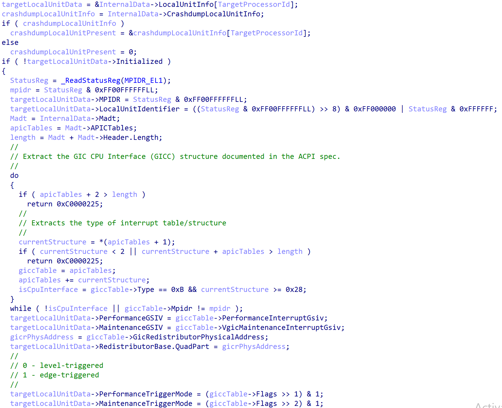
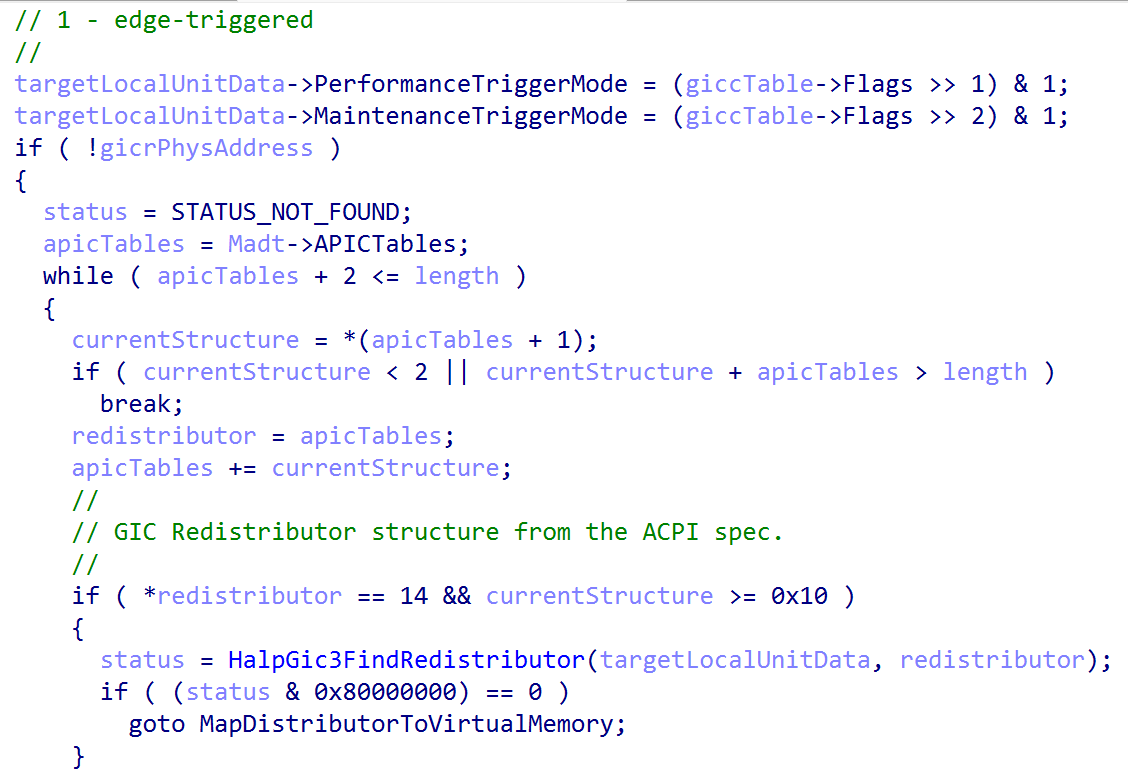
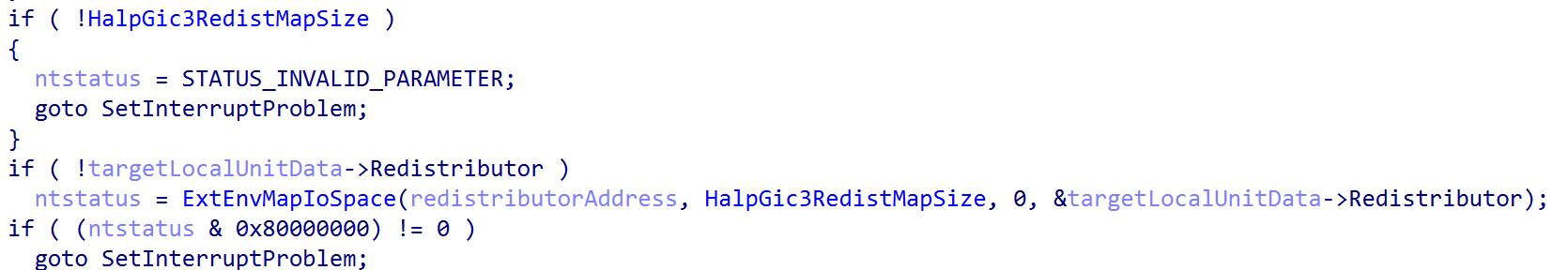
MPIDR_EL1 register handling. Source: original article.Finally, the redistributor is mapped into virtual memory (with the mapping size given by HalpGic3RedistMapSize, computed in nt!HalpGic3RegisterIoUnit). This marks the local unit as initialized (GIC3_LOCALUNIT_INFO->Initialized = 1).
Next, the appropriate Interrupt Controller System Register Enable (ICC_SRE_ELX) register is read. A nuance worth calling out: ICC_XXX replaces GICC_XXX here. GICC_XXX refers to legacy registers. In GICv3, per the documentation, the physical CPU-interface registers are prefixed with ICC, and virtual CPU-interface registers are prefixed with ICV instead of GICV. That is why, in Windows, you will only see writes to the ICC_XXX system registers.
The kernel always sets bit 1 if it is not already set — the ICC_SRE_ELX.SRE bit, which determines whether the memory-mapped or system-register interface is used to interface with the GIC CPU interface for the target CPU. Setting it to 1 selects the system-register interface (the GIC documentation also states that system registers must be used when affinity routing is in use for all enabled security states). Some items, like the GIC distributor, are always memory-mapped.
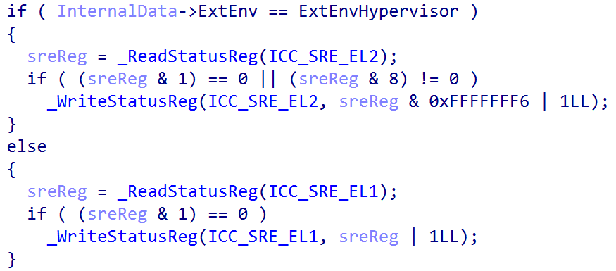
ICC_SRE_ELX configuration. Source: original article.The kernel then disables group 1 interrupts for the time being (there are only 2 groups: group 0 is for interrupts handled at EL3, so group 1 is for everything else in the current exception and security level — remember that Windows does not use the traditional security levels, since it already separates “secure and non-secure worlds” via VTLs). It sets the interrupt priority filter to 0 (the CPU will accept only interrupts with a priority higher than 0; 0 is the highest priority, so this effectively disables all interrupts until the local unit is configured). It also sets the interrupt-controller binary point register for EL1 to a value of 3 — the minimum value required.
Briefly: interrupt grouping in the GIC groups interrupts by a set of characteristics aligned to the ARM security and exception model — by security state (non-secure / secure worlds) and exception level. Windows only uses group 1 interrupts, and specifically only in the non-secure state. This can be confirmed by reading the GICD_CTLR.EnableGrpXXX values from the GIC distributor — which describe which groups of interrupts are enabled — and also by parsing ntoskrnl.exe and hvaa64.exe (Hyper-V) for a lack of writes to the ICC_IAR0_EL1 / ICC_EOIR0_EL etc. registers, where 0 refers to group 0 (the interrupts associated with EL3, the “bridge” between non-secure and secure worlds).
GICD_CTLR.EnableGrp0= 0GICD_CTLR.EnableGrp1NS= 1 (Non-Secure)GICD_CTLR.EnableGrp1S= 0 (Secure)
Moving on, nt!HalpGic3InitializeLocalUnit fills out additional GIC redistributor information in the GIC3_LOCALUNIT_INFO structure. First, information of interest from the LPI configuration table tracked by the in-scope CPU’s GIC redistributor is added to the “internal data” (tracked via nt!HalpGic3). This is achieved by accessing the GICR_PROPBASER register from the GIC redistributor, which specifies the LPI configuration table.
The LpiConfig member of GIC3_DATA (of type LPI_CONFIG_TABLE_ENTRY) holds the virtual address of the target CPU’s LPI table (and all other LPI configuration tables). Note that the redistributor’s format is documented by ARM and is not part of the Windows symbols.
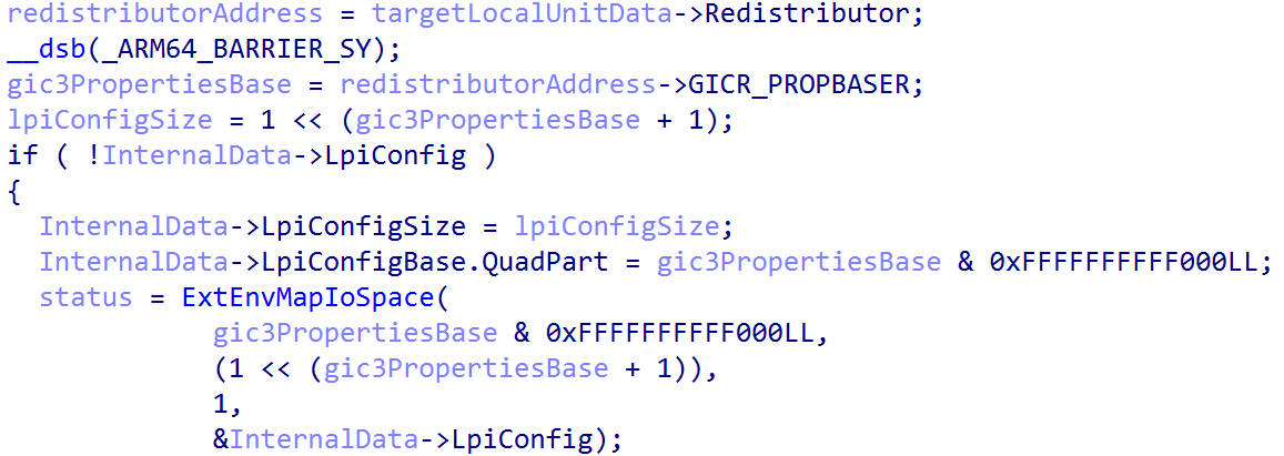
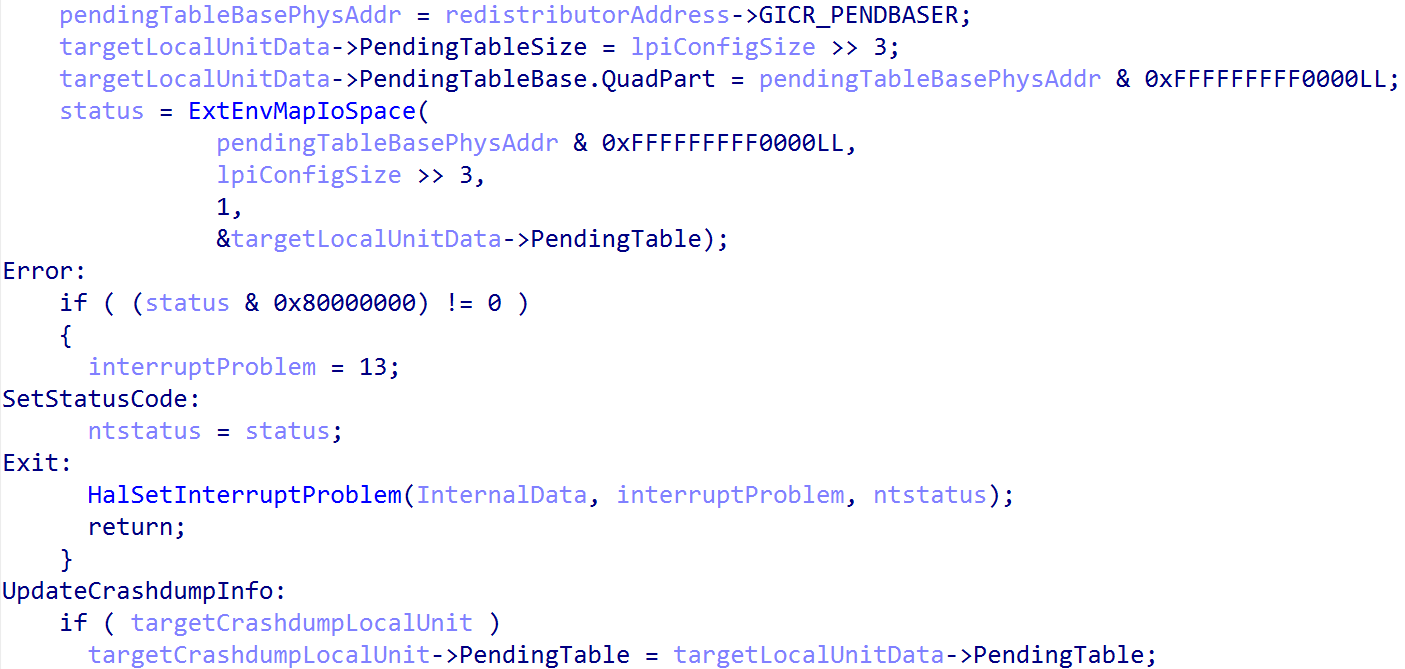
GICR_PROPBASER. Source: original article.Next the LPI pending table is mapped into virtual memory; this time it is tracked through the local unit’s structure (GIC3_LOCALUNIT_INFO) as the PendingTable member. This is achieved by accessing the GICR_PENDBASER register from the GIC redistributor’s memory-mapped interface. The global GIC data structure (nt!HalpGic3) that represents, in virtual memory, the state of the GIC also updates the per-CPU crash-dump information. The pending LPI table is added to the crash-dump information as well.
One thing worth calling out: starting at an offset of 0x10000 (64 KB) after the GIC redistributor registers (which contain GICR_CTLR, etc.) come the GIC redistributor registers responsible for configuring SGIs and PPIs. They are also documented by ARM, and the GIC documentation also calls this out:
Each Redistributor defines two 64KB frames in the physical address map:
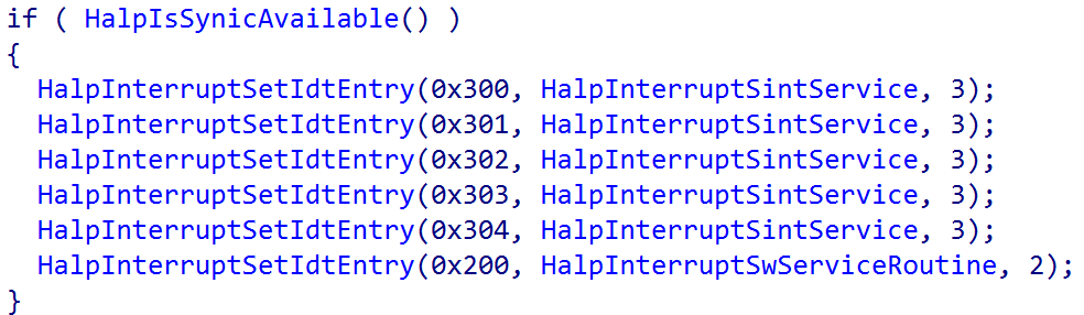
This means that starting at GIC3_LOCALUNIT_INFO->Redistributor + 0x1000 are the SGI / PPI redistributor registers. From the SGI / PPI registers, GICR_ICENABLER0 (the Interrupt Clear-Enable Register 0) is configured. It is set to enable the forwarding of all interrupts to the GIC redistributor by writing a value of 1 to the target register, while remaining sensitive to any SGIs (GICR_ICENABLER0 encapsulates both SGIs and PPIs) that are reserved for the ARM Firmware Framework A-Architecture (FF-A). Specifically, the FFA_FEATURE call retrieves the interrupt ID (INTID) for the Schedule Receiver Interrupt (SRI) and ensures that ID is always disabled. However, this only applies in some operating environments (such as without Hyper-V present); on the test machine, nt!HalpFfaEarlyErrorRecords (an array of errors associated with initializing FF-A) reports STATUS_NOT_SUPPORTED, translated from the FFA_ERROR code of NOT_SUPPORTED — so there is no need to worry about “special” handling of SGIs associated with the FF-A. There is no SGI reserved for the FF-A’s SRI. This can be further verified by checking the presence of nt!HalFfaSupported and nt!HalFfaInitialized, which denote FF-A support and state.
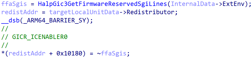
GICR_ICENABLER0. Source: original article.Finally, one of the last things nt!HalpGic3InitializeLocalUnit does is configure the ICC_CTLR_EL1 system register (the Interrupt Control Register). If the operating environment is ExtEnvHypervisor, ICC_CTLR_EL1.EOIMode (End-of-Interrupt) is set. Otherwise (as is the case here, since our operating environment is ExtEnvHvRoot) EOIMode is set to 0. End-of-Interrupt (EOI) refers to a specific action taken to indicate that the software routine which handled a target interrupt has finished. A value of 0 means that a write to, for example, ICC_EOIR1_EL1 (for group 1 interrupts) is responsible for both “priority drop” and deactivation of an interrupt, whereas a value of 1 means a write to a separate register is required for deactivation. ARM’s GIC documentation states that the EOIMode == 1 mode is used for virtualization purposes.
nt!HalpGic3InitializeLocalUnitData ends by re-enabling interrupts now that the local CPU unit (redistributor and CPU interface) is configured, via ICC_IGRPEN1_EL1. Later, nt!HalpInterruptMarkProcessorStarted marks the processor as “started” for interrupts.
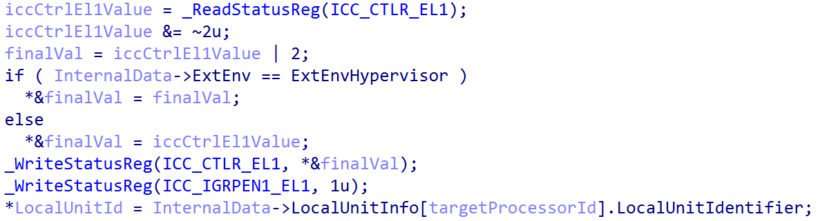
ICC_CTLR_EL1 configuration. Source: original article.After nt!HalpGic3InitializeLocalUnit data exits, a per-CPU (technically per-core — the test system has 12 cores) structure, INTERRUPT_TARGET, is filled out and managed by the symbol nt!HalpInterruptTargets. This is done via nt!HalpGic3ConvertId. These structures carry additional information about the CPU schema, such as whether the CPU resides in a cluster, along with CPU ID information. The CPU ID information is effectively the previously mentioned affinity values from the MPIDR_EL1 system register.
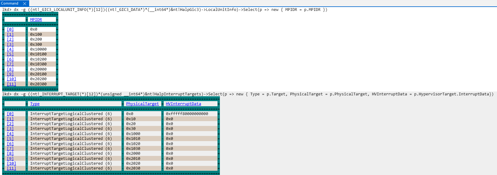
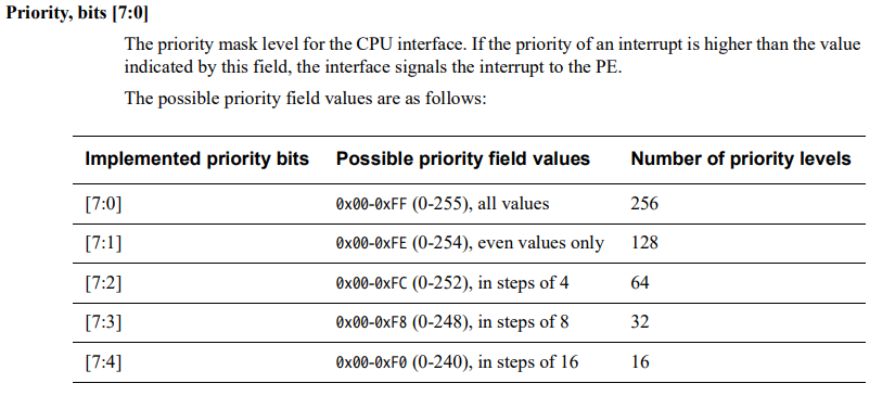
INTERRUPT_TARGET structures. Source: original article.After configuring the interrupt targets (representing the targets to which interrupts can arrive), the real per-CPU interrupt priority is set via nt!HalpGic3SetPriority (it was temporarily set to 0 earlier). Once the local unit is up, the priority is updated per CPU to 0xF0. 0xF0 is 0b11110000 in binary, and bits 0:7 in ICC_PMR_EL1 (the priority register) make up the priority level. A value of 0xF0 indicates that the total number of priority levels is 16 — priority levels 0–15 will be handled by each CPU interface.
Once the priority level has been configured for each CPU, execution transfers to nt!HalpGic3InitializeIoUnit, which takes a parameter to the GIC3_DATA we have been referencing. Specifically, GIC3_DATA->IoUnit — the GIC distributor structure’s virtual address — is configured. This function is not called per CPU; it is called to further configure the singular GIC distributor. By “GIC distributor structure” we mean the ARM-documented memory-mapped registers like GICD_CTLR, GICD_TYPER, etc. — this is where the rest of those registers are configured.
GIC3_DATA->InputLineCount is configured first. This is done by extracting GICR_TYPER->ITLinesNumber. According to ARM documentation, ITLinesNumber is the “number of SPIs divided by 32”, so InputLineCount is simply GICR_TYPER->ITLinesNumber * 32. This refers to the maximum SPI INTID and also to the number of interrupt lines available (lines = interrupt IDs in this context), although some interrupt sources may share a line.
Extended SPI support was mentioned earlier. It is indicated by GICD_TYPER->ESPI, and the test machine has extended SPI support. When extended SPI support is enabled, bits 31:27 in GICD_TYPER are no longer “reserved” but instead refer to ESPI_range. This is extracted and stored in ExtendedInputLineCount to indicate the maximum supported extended SPI INTID.
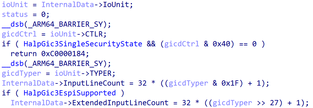
InputLineCount and GICD_ICENABLER configuration. Source: original article.From here, Windows unconditionally clears GICD_CTLR.EnableGrp1NS, represented by bit 1 (from index 0) — disabling interrupts in the non-secure group 1 group. This is a temporary measure while the rest of the GIC distributor is configured. Next, if the GIC distributor (again, memory-mapped in physical memory and not yet fully configured by the OS) has GICD_CTLR.ARE_S configured — which enables affinity routing in the secure state — or if ARE_S is not set (in this case ARE_S is set to 1, so either way it will be set to 1), the interrupt lines supported are further configured.
The GICD_ICENABLER<n> register, part of the distributor, contains a bitmask corresponding to a particular interrupt that denotes whether forwarding of that interrupt from the distributor to the target CPU interface is allowed. nt!HalpGic3InitializeIoUnit begins by configuring all of the GICD_ICENABLER registers (4 bytes each) to a value of 0xFFFFFFFF — which prevents any interrupts from being forwarded to the target CPU interface.
Next, all of the GICD_IROUTER<n> registers (and all GICD_IROUTER<n>E registers for extended interrupts) for the GIC distributor (still being configured) are all set to 0. A GICD_IROUTER register, 8 bytes, contains the necessary information for routing a particular SPI (SPI, not SGI, etc.) for a particular interrupt number.
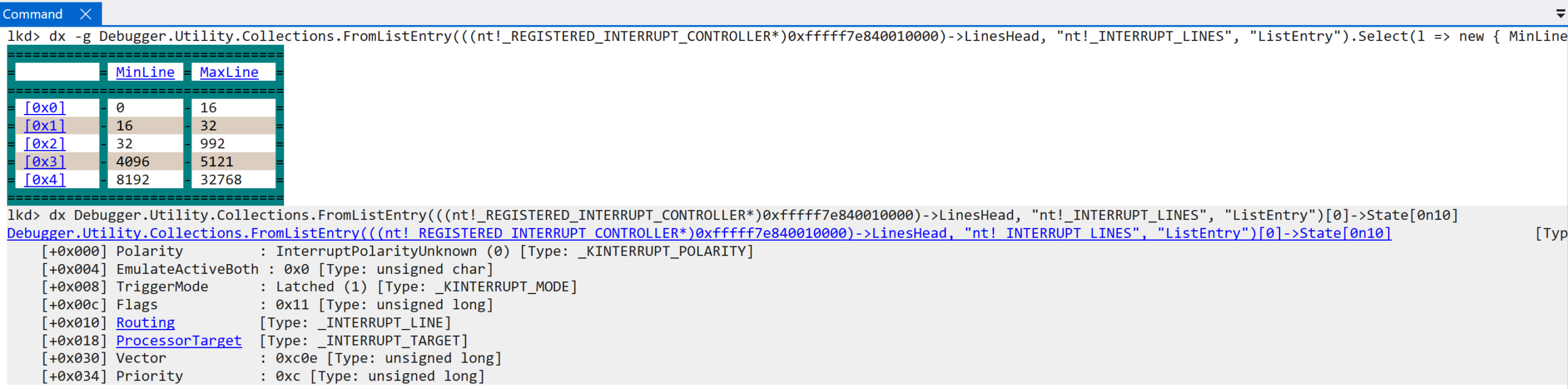
Finally for this function, if the local unit data has not been marked as initialized, a call to nt!HalpGic3DescribeLines occurs. This fills out INTERRUPT_LINES structures, maintained in a doubly-linked list, which define the type of interrupt line (we have already discussed “lines”; the lines on which an interrupt arrives are associated with a particular interrupt source like an SGI or PPI), internal line state, etc. All interrupt lines are tracked through the registered interrupt controller via the LinesHead linked-list head.
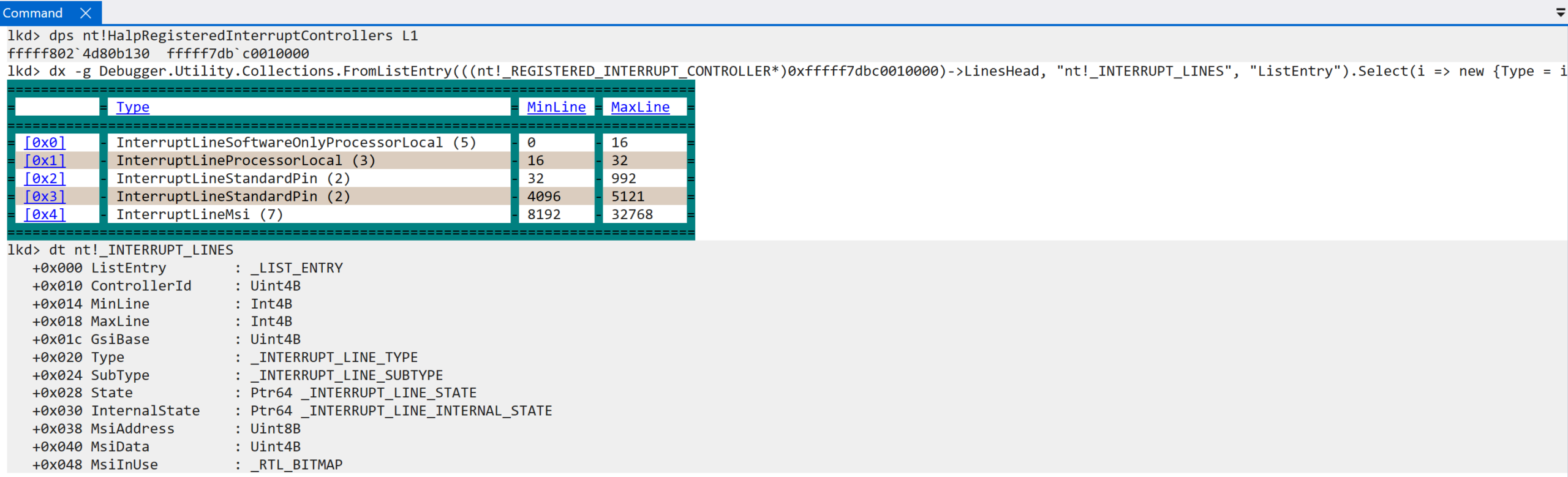
The “max” and “min” line values refer to the values in which an interrupt ID resides — the “lines” on which interrupts can arrive (an interrupt is tied to an ID). For example, the interrupt line described as InterruptLineMsi, referring to message-based interrupts, can have an interrupt ID from 8192 – 32768, as outlined in the ARM documentation. The INTERRUPT_LINES list tracks information about each of the interrupt sources and all of the lines on which an interrupt can arrive (there is a difference between what is possible and what is supported — Windows does not support handling every single interrupt ID). The initialization of all interrupt lines then results in the GIC3_DATA structure (nt!HalpGic3) being fully initialized (InternalData->Initialized = 1) and group 1 non-secure interrupts (GICD_CTLR.EnableGrp1NS) being re-enabled (previously cleared). This completes the functionality encapsulated by nt!HalpInterruptInitializeController.
If interrupt initialization has succeeded up to this point, the entire MADT (Multiple APIC Description Table, discussed earlier) is parsed via nt!HalpInterruptParseMadt. Technically this happens as a result of another call to nt!HalpInterruptParseAcpiTables. That function was one of the first invoked in nt!HalpInitializeInterrupts — which kicked off interrupt initialization. However, a boolean gates whether the MADT is actually parsed (denoting whether an interrupt controller has yet been registered). This second call now passes true, so the MADT is parsed.
nt!HalpInterruptParseMadt determines which features are available for the interrupt controller — the layout of the GIC distributor, redistributors, etc. Particularly interesting: comparing the code between x64 and ARM, there is effectively 100% overlap. For instance, ARM machines use a GIC, but there is also code that validates APICs; for x64, there is code that validates GICs. For ARM analysis, the parsing is done to gather additional information about the specifics of the interrupt controller implementation (GIC), for determining whether, for example, interrupts need to be “hyper-threading aware” (nt!HalpInterruptHyperThreading), a list of non-maskable interrupt sources (NMI), etc.
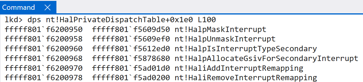
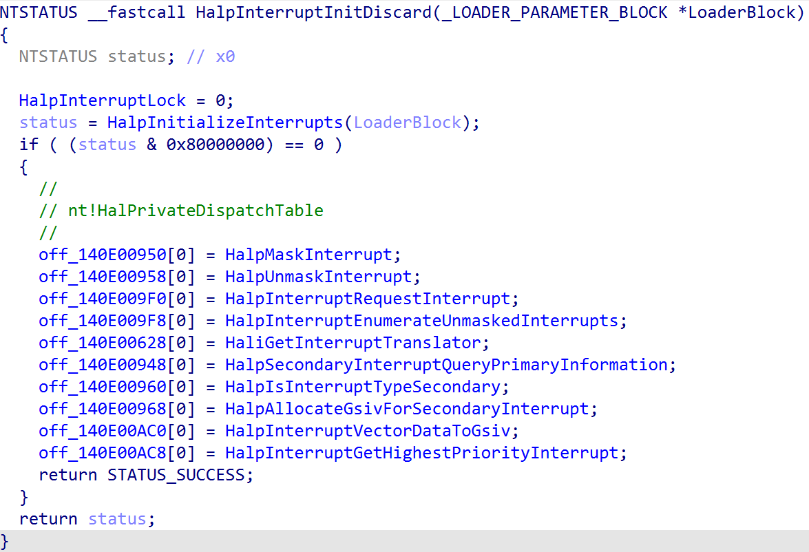
Finally, the last part of interrupt initialization is the initialization of IPIs (a common name for SGIs — inter-processor interrupts where cores can send interrupts to other cores) via nt!InterruptInitializeIpis. Once that completes, the HAL’s private dispatch table (nt!HalPrivateDispatchTable) is updated with a few interrupt-relevant routines.
Interrupt Delivery and Handling — Windows on ARM
With the interrupt controller now configured and initialized, the OS can start receiving interrupts in software. As mentioned in an earlier blog post, even interrupts are delivered as “exceptions” on ARM.
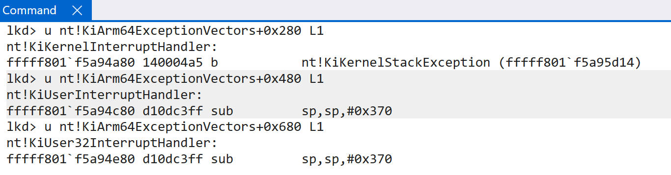
This is obviously one of the main differences between x64 and ARM: how interrupts arrive in software and how the high-level handler then invokes the interrupt-specific handler (for example, there is no IDT on ARM and there is no nt!KiIsrThunk or nt!KiIsrLinkage). Interrupts are dispatched as exceptions — typically asynchronous exceptions, meaning the exception is external to the CPU — so it is worth quickly looking at how exception dispatching reaches the high-level interrupt handler on ARM64 Windows. Windows ARM systems maintain a vector of exception handlers via the symbol nt!KiArm64ExceptionVectors (for EL1 / kernel-mode, stored in the VBAR_EL1 system register). This is not an array of function pointers but instead a large blob of code, accessible through different function names. The entire stub is self-contained. ARM documentation defines a fixed layout for these tables (see “AArch64 vector tables”). For our purposes, the exception handler associated with handling interrupts that occur while execution is in user-mode is located at VBAR_EL1 + 0x80 (nt!KiKernelSp0InterruptHandler). The CPU itself computes the necessary offset into the exception table and invokes the target function — not software.
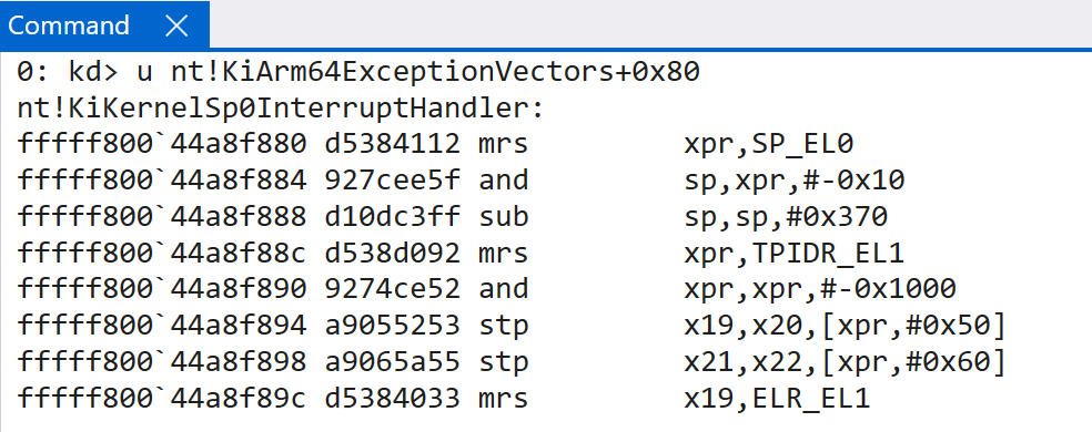
nt!KiArm64ExceptionVectors in VBAR_EL1. Source: original article.Interestingly, that is not the end of the story. There is not just one single handler. Depending on the state of the CPU (where execution was) when the interrupt happens, a different exception (interrupt) handler may be invoked. If execution was in kernel-mode when the interrupt occurred, the offset changes to 0x280 and the target becomes nt!KiKernelInterruptHandler. nt!KiUserInterruptHandler (offset 0x480) is invoked when an exception goes into a higher exception level (EL0 -> EL1) and at least one of the lower exception levels is running ARM64. nt!KiUser32InterruptHandler is at offset 0x680 and is invoked for the same exception type, but when all lower exception levels are ARM32 (different exception levels can be different architectures).
Interrupts on Windows will always take an exception into EL1 — this is where the various interrupt handlers live. Given that, the SPSR_EL1 system register helps us understand why a particular exception was taken into EL1. Because PSTATE is not directly accessible through a single system register, the Saved Program Status Register (SPSR) acts as a snapshot of relevant information about the current state of the CPU. This is needed for preserving and later restoring the state of the CPU at the time the exception (interrupt in our case) was handled.
After the current state of the CPU is known, there are a few more items needed before the interrupt can be dispatched to software. The first is that the CPU needs to know where to return execution after the interrupt. A special system register, ELR_EL1 (the exception link register), holds this address — typically the next instruction to be executed (e.g., the first instruction that has not yet completed). The operation also needs a specific stack. At a higher level, in software, interrupt service routines (ISRs) already have special reserved stacks for interrupt handling. Kernel stack space is limited, and we want to ensure ISRs are not handled on stacks without remaining space. At a lower level, the same thing happens conceptually: the CPU itself must target a specific stack (while software on Windows handles the ISR stacks). Without complicating things, interrupts that occur in EL0 and are then trapped into EL1 are handled on the stack pointer (SP) stored in SP_EL0. For interrupts that occurred when execution was already at EL1, SP_EL1 would be used instead. This is why the interrupt handler for interrupts that happened while execution was in EL0 has Sp0 in the function name. Interrupts interrupt some sort of execution and need to be quick. The EL0 stack is the stack at whatever time the interrupt occurred in EL0.
Our example will look at interrupts that occurred while execution was in EL0 (nt!KiKernelSp0InterruptHandler). As mentioned, the first few things that happen (from the CPU’s perspective, transparent to the interrupt handler) are:
SPSR_EL1is updated with the currentPSTATE(the current state of the CPU), so the state can be restored later.- The actual
PSTATEis updated with information about the new execution environment (EL1, because the interrupt is trapped into EL1). - The CPU actually executes the target interrupt handler (and selects the proper stack — in this case the EL0 stack).
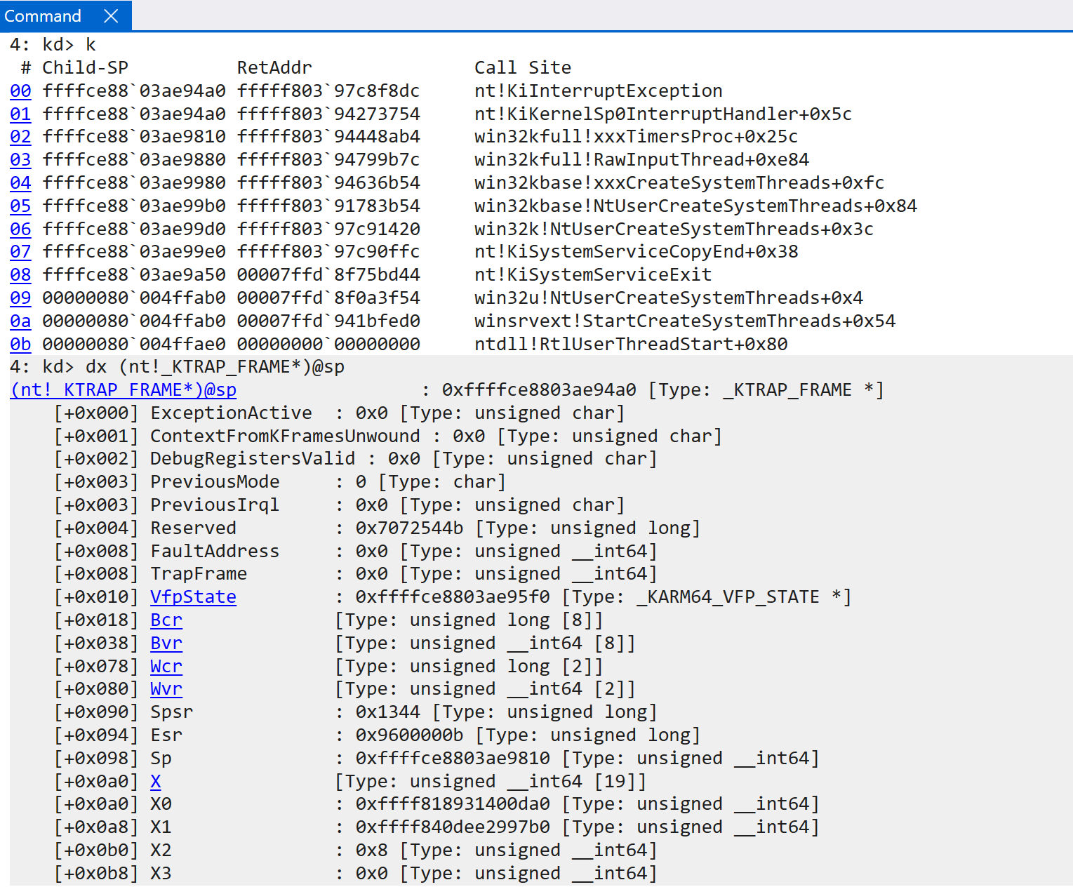
Execution is now in the interrupt handler (obviously, setting a breakpoint on the interrupt handler is not a great idea!). The first thing nt!KiKernelSp0InterruptHandler does is update the current execution environment as far as Windows is concerned. This includes allocating space on the SP_EL0 stack and extracting a few pieces of information from the current KPCR structure (TPIDR_EL1 / x18 / xpr all hold the KPCR, as noted in the previous blog). The ELR_EL1, SPSR_EL1, ESR_EL1, and SP_EL0 registers are preserved. Once preserved, the new SP_EL0 stack pointer is populated (since the old one is now preserved). The previously mentioned stack allocation is then used to store a trap frame, which is passed to the target interrupt-handling operation (via nt!KiInterruptException). The target trap frame eventually passed to nt!KiInterruptException is found directly on the stack (execution is not returned from a return address on the stack since we are dealing with an exception — the exception link register and ERET are used). It still follows the typical calling convention by also copying this value into X0.
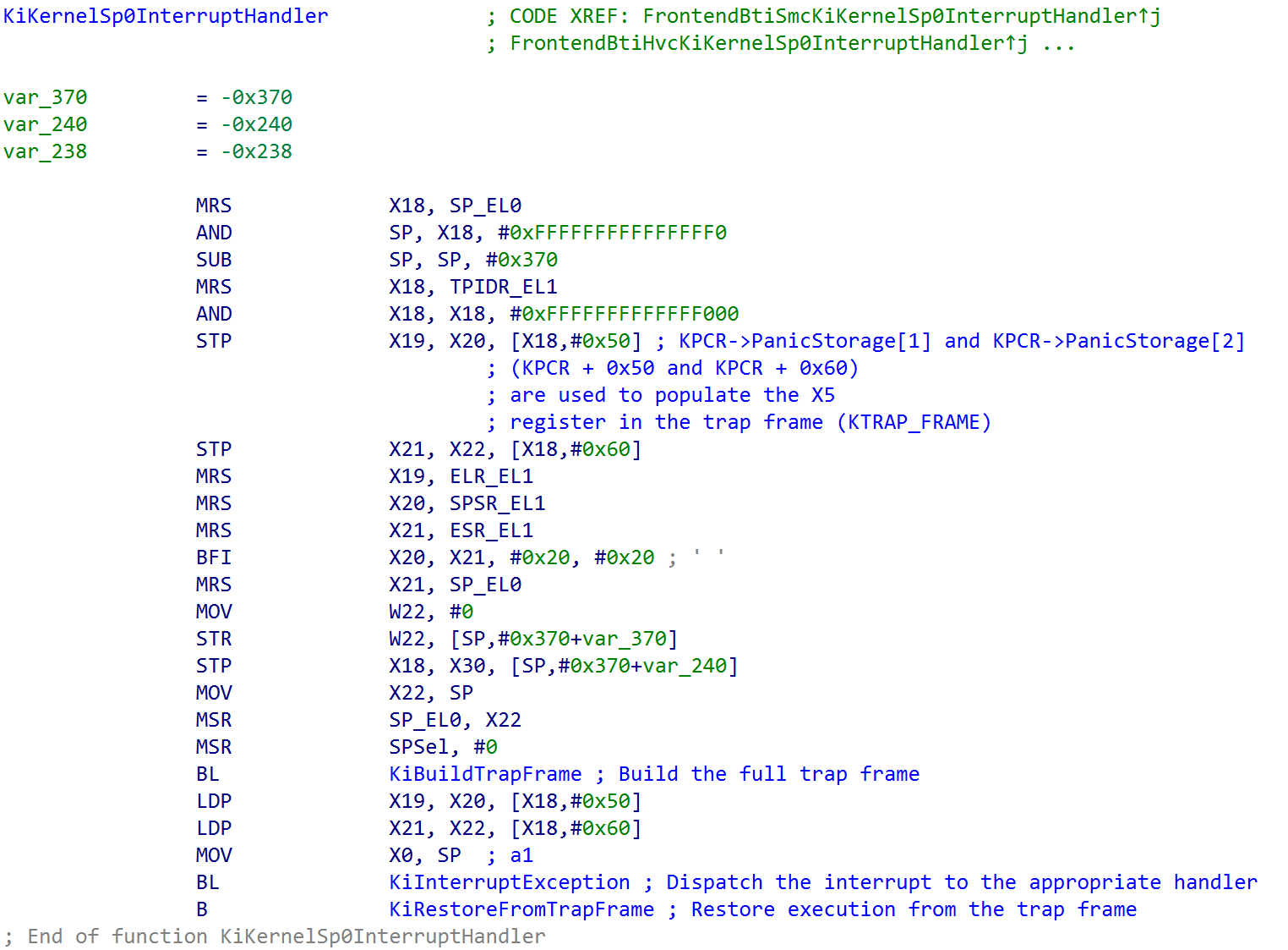
nt!KiKernelSp0InterruptHandler entry. Source: original article.nt!KiBuildTrapFrame invokes nt!KiCompletePartialTrapFrame (which currently holds only the previously mentioned system registers, EL0 stack, etc. in the trap frame) to grab more of what is needed. This includes the various debug registers and the SVE (Scalable Vector Extension) state. This function uses the stack space as the “output” parameter to store the final trap frame, which is passed as the single argument to nt!KiInterruptException — which dispatches the correct interrupt handler in software.
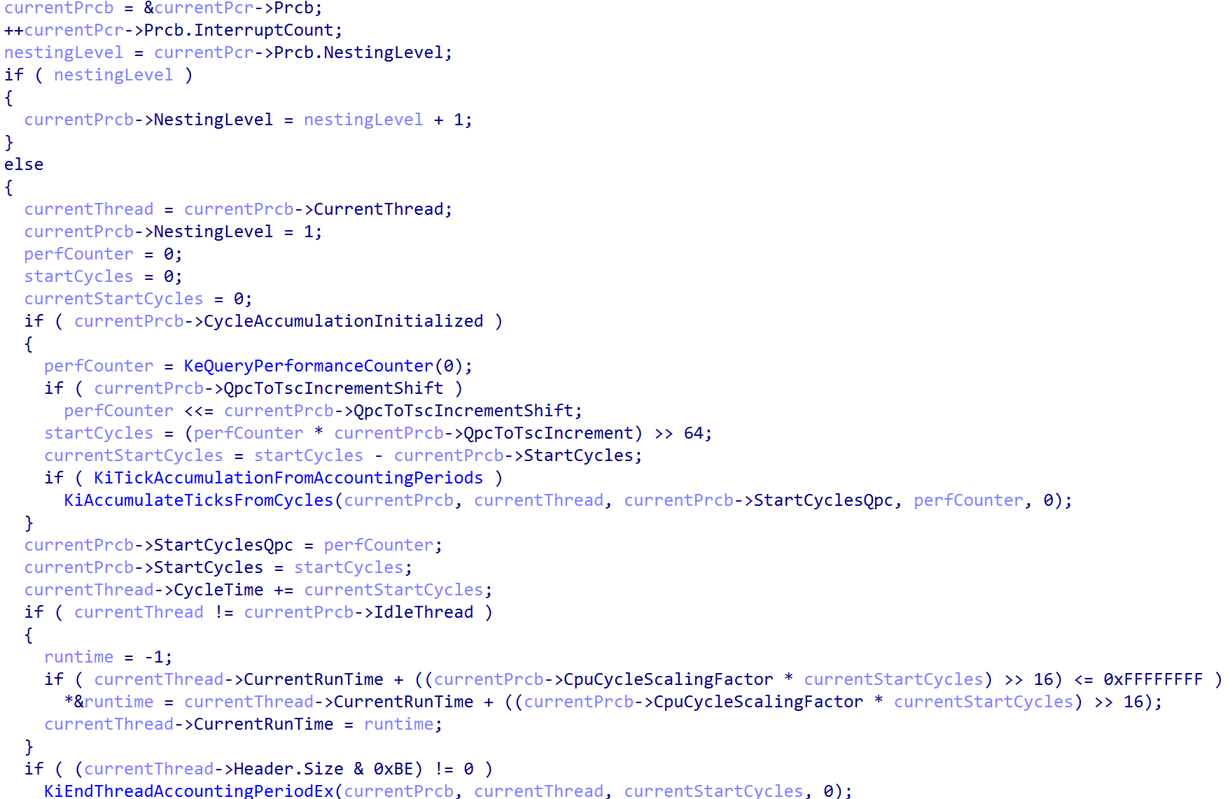
nt!KiBuildTrapFrame and nt!KiCompletePartialTrapFrame. Source: original article.Before interacting with the interrupt controller (HalpInterruptController), a few housekeeping items happen: incrementing the interrupt count and nesting level (if applicable — e.g., this is a nested interrupt) and updating the current CPU’s cycles / current runtime.
Note that in the process of writing this blog, my machine crashed a few times. Due to this, some of the values may change.
After this, the first bit of interrupt dispatching logic is called — via nt!HalpGic3AccceptAndGetSource. This function simply reads from the ICC_IAR1_EL1 system register, which achieves two things: a read acknowledges, from software, the interrupt that has been signalled, and it provides the caller with the target interrupt ID (INTID). The returned value can also be one of the “special” interrupt values — including 0x3ff / 1023 — denoting that there is no pending interrupt with high enough priority to be forwarded to the CPU (or that the interrupt is not appropriate for the target CPU).

nt!HalpGic3AccceptAndGetSource reads ICC_IAR1_EL1. Source: original article.After acknowledgement, execution continues by grabbing the registered interrupt controller we have already seen and iterating over all the known / valid interrupt lines (INTIDs), comparing them with the value provided by the interrupt acknowledgement register.
Earlier in this article we configured various KINTERRUPT objects. Each, in its Vector field, contained what we saw was a target IRQL at which the target interrupt should be handled. Each vector value is tracked in the registered interrupt controller’s INTERRUPT_LINES member. Specifically, for a range of interrupt IDs the interrupt ID itself can be used as an index to find the appropriate information about how the target interrupt ID is to be handled. This is how the Vector is fetched — giving us the target IRQL the CPU should be raised to in order to handle the target interrupt.
After the IRQL is raised (or lowered) to the target IRQL, the “main brain” of the routing operation, nt!KiPlayInterrupt, is invoked (unless there is not enough stack space — in which case KxSwitchStackAndPlayInterrupt is invoked, using the current CPU’s ISR — Interrupt Service Routine — stack). nt!KiPlayInterrupt has the following prototype:
KiPlayInterrupt (
   _In_ KTRAP_FRAME* TrapFrame,
   _In_ VectorFromInterruptLineData,
   _In_ UINT8 Irql,
   _In_ UINT8 PreviousIrql
    );
This brings up the conversation about “vectored interrupts”. ARM64 does not have the same concept of vectored interrupts as x64 — where the IDT can be directly indexed by the CPU itself. Instead, as shown, ARM implements a generic interrupt controller: there is one single interrupt handler, and software must then find the appropriate interrupt handler. On ARM, we still have the Interrupt Descriptor Table (IDT), but it is not accessed directly by the CPU itself — only the vector of exception handlers is directly invoked by the CPU.
Instead, the vector value from the interrupt-line state (and the KINTERRUPT object itself) is used as an index into the IDT — but this is a software-defined vector, not a vector “contract” required by the interrupt controller (only the VBAR_EL1 table has a strong contract, where the high-level interrupt handler must be present).
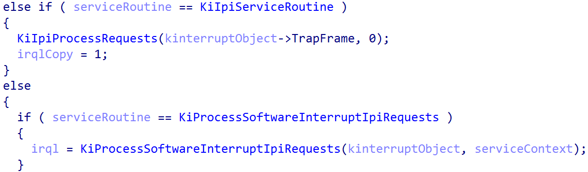
This allows us to extract the target KINTERRUPT object. From there, the target ServiceRoutine can be extracted, and a large if / else statement determines whether the interrupt needs further processing based on the target service routine (ISR).
KINTERRUPT.ServiceRoutine. Source: original article.After the target interrupt handler is invoked, nt!KiPlayInterrupt is responsible (if applicable) for additional cleanup — decrementing the nested interrupt level, updating the CPU cycle count, etc. Execution then returns to the caller, nt!KiInterruptException, which calls nt!HalpGic3WriteEndOfInterrupt — which simply writes to the ICC_EOIR1_EL1 system register the interrupt ID that was handled.
The last thing that needs to happen is restoring the execution state that was in progress when the interrupt took place. This happens via nt!KiRestoreFromTrapFrame — a generic function called by many exception handlers that restores execution state (via the preserved trap frame shown at the beginning of this section) and performs an ERET, based on the target exception link register value, back to EL0.
Virtualization and Interrupts
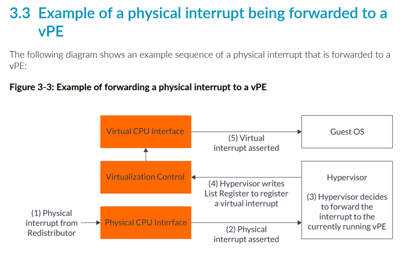
Virtual interrupts are a must for systems running virtualization software like Hyper-V. Because the Windows OS itself is virtualized, virtualization and virtual interrupts are very important constructs that have not yet been covered. There is still an extra traversal that happens between EL0, EL1, and now EL2 with the addition of the hypervisor.
For virtual interrupts, the hypervisor configuration register (HCR_EL2) is responsible for configuring the routing of physical interrupts. As shown earlier, Hyper-V configures this register in its entry point. Hyper-V directly configures HCR_EL2.FMO and HCR_EL2.IMO, which respectively route physical interrupts (IRQs and FIQs) to EL2 (Hyper-V). However, HCR_EL2.TGE is not enabled for Hyper-V (trap general exceptions). Given that, there is some nuance about what these interrupts look like. From the ARM documentation, when HCR_EL2.IMO is set to 1:
When executing at any Exception level, and EL2 is enabled in the current Security state:
What this actually means is that physical IRQs are not routed to EL2. Instead, virtual IRQs (virtual interrupts) are enabled in the hypervisor configuration Hyper-V applies. A quick distinction: “virtual interrupts” is a term used by both Hyper-V (Windows) and ARM. ARM knows nothing about the OS when it comes to virtual interrupt configuration. Hyper-V, as we will see, also implements an additional level of abstraction for virtual interrupts (especially for guests). Windows Internals, 7th Edition, Part 2 has an entire section on “Virtual interrupts” — but it is worth first describing how ARM defines them and then moving to the Hyper-V details. Virtual interrupts, in general, represent interrupts seen by VMs / guests.
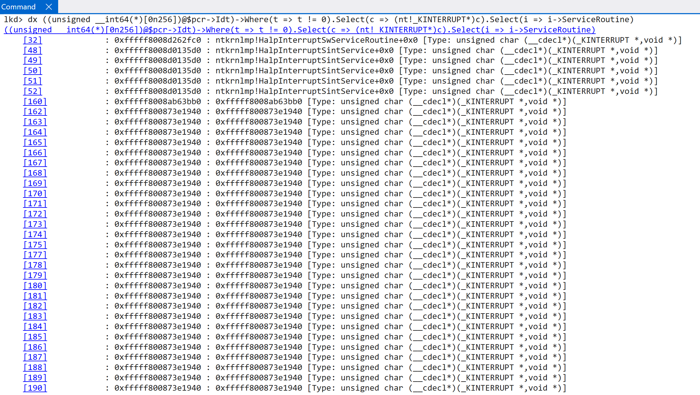
According to the TLFS, ARM64 systems expose a virtual GIC (done by software in cooperation with the CPU, as called out by ARM — the distributor, redistributor, etc., do not themselves provide virtualization for these, so help is required from software running in EL2; this is beyond the scope of this post and is achieved by the hypervisor), which “conforms to the ARM GIC architecture specification”. This means our dynamic analysis has technically been dealing with a virtual GIC — transparently, because as “the guest” we simply access the “normal” interrupt-controller registers (GICv3 has the ability to virtualize the interrupt controller). Even though the root partition is often “enlightened” with extra information that guests may not be privy to, both root and guest partitions go through the virtualized GIC. This is also why the EXT_ENV member of the registered interrupt controller matters — and why one of the options is ExtEnvHvRoot for the root partition. This can be seen by comparing the output of the IDTs between a true guest and the OS living in the root partition.
Guest:
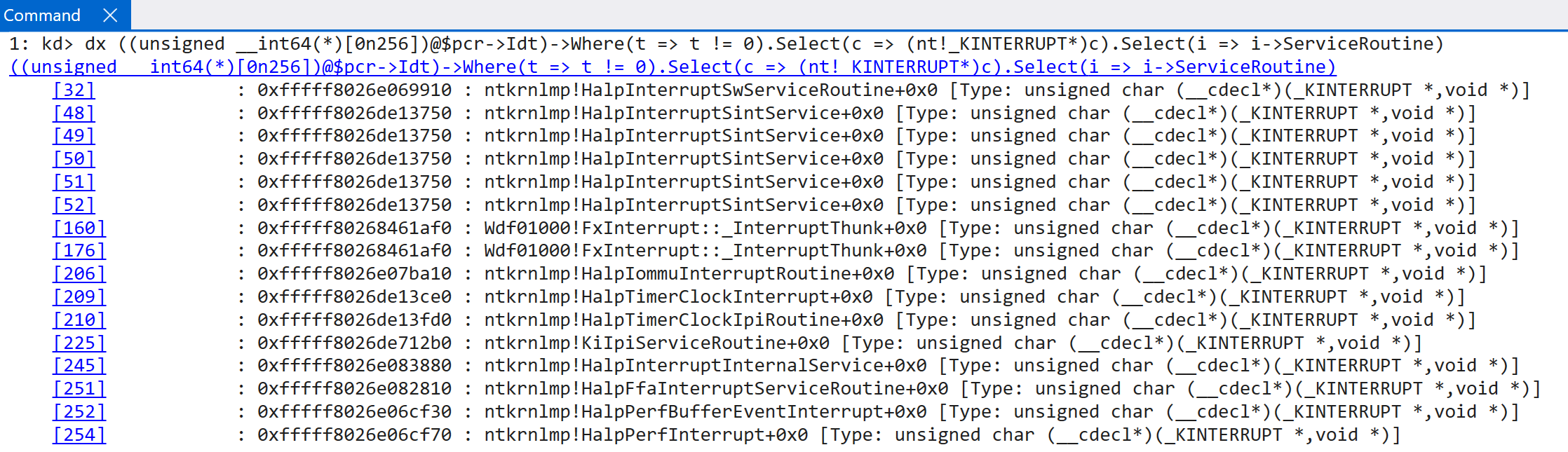
Root partition (many other KINTERRUPT objects are truncated):
Before drifting too far, back to the “ARM” view of virtual interrupts. ARM’s documentation is very helpful here. First, virtual interrupts target virtual CPUs (not VMs). The hypervisor uses ICH_XXX instead of the ICC_XXX interrupt registers to interact with virtual interrupts (which also means virtualization of the GIC is a “hardware” construct in the sense that there are dedicated system registers to configure the virtual GIC’s functionality). Parsing a list of system-register writes in Hyper-V reveals (obviously) the presence of virtual interrupt configuration and management (ICH_HCR_EL2 is effectively the virtual interrupt configuration register):
0x14022760c sub_1402275D0 MSR c12 #4 MSR ICH_HCR_EL2, X8
As Windows Internals, 7th Edition, Part 2 calls out, Hyper-V is configured (but does not leverage) to support up to 16 virtual interrupt types — matching what ARM supports. One virtual interrupt is represented by a single ICH_LR<N>_EL2 register, where N is between 0 and 15 (16 total). A hypervisor write to one of these registers corresponds to the generation of a virtual interrupt. Parsing Hyper-V, we can see several instances of virtual interrupt generation:
0x140228a7c   sub_140228A30   MSR c12 #4   MSR ICH_LR1_EL2, X8
0x140228af0   sub_140228A30   MSR c12 #4   MSR ICH_LR0_EL2, X8
0x140228bdc   sub_140228A30   MSR c12 #4   MSR ICH_LR2_EL2, X8
0x140228c38   sub_140228A30   MSR c12 #4   MSR ICH_LR15_EL2, X8
0x140228c48   sub_140228A30   MSR c12 #4   MSR ICH_LR14_EL2, X8
0x140228c58   sub_140228A30   MSR c12 #4   MSR ICH_LR13_EL2, X8
0x140228c68   sub_140228A30   MSR c12 #4   MSR ICH_LR12_EL2, X8
0x140228c78   sub_140228A30   MSR c12 #4   MSR ICH_LR11_EL2, X8
0x140228c88   sub_140228A30   MSR c12 #4   MSR ICH_LR10_EL2, X8
0x140228c98   sub_140228A30   MSR c12 #4   MSR ICH_LR9_EL2, X8
0x140228ca8   sub_140228A30   MSR c12 #4   MSR ICH_LR8_EL2, X8
0x140228cb8   sub_140228A30   MSR c12 #4   MSR ICH_LR7_EL2, X8
0x140228cc8   sub_140228A30   MSR c12 #4   MSR ICH_LR6_EL2, X8
0x140228cd8   sub_140228A30   MSR c12 #4   MSR ICH_LR5_EL2, X8
0x140228ce8   sub_140228A30   MSR c12 #4   MSR ICH_LR4_EL2, X8
0x140228cf8   sub_140228A30   MSR c12 #4   MSR ICH_LR3_EL2, X8
0x140228fe4   sub_140228F78   MSR c12 #4   MSR ICH_LR1_EL2, X8
This register includes important information — the virtual interrupt ID (vINTID), interrupt priority, etc. When the hypervisor writes to the target register, the virtual interrupt is injected into the guest. ARM’s documentation provides a nice visual here.
ICH_LR<N>_EL2. Source: original article.So we now have the underlying mechanism by which the hypervisor, using the CPU registers and hardware functionality exposed by GICv3, delivers a virtual interrupt to a target virtual CPU. However, Hyper-V adds another level of abstraction — the synthetic interrupt controller — in order to deliver interrupts to synthetic devices (virtualized keyboards, mice, etc.). The synthetic interrupt controller delivers two types of interrupts to virtual CPUs: those that come from hardware / devices (external) and synthetic interrupts (which come from Hyper-V and are not generated by hardware).
The TLFS defines the synthetic interrupt controller as a set of extensions provided in addition to the existing interrupt-controller features. Hyper-V uses it to deliver interrupts generated from physical hardware to the guest (or root partition, which is the host OS) and to add an additional layer of abstraction over various message channels (defined by the TLFS) for other special kinds of interrupts — such as the hypervisor directly delivering a message to a target partition (in the case of an intercept, for example) or inner-partition communication. Some of these message types can be seen below:
typedef enum
{
   HvMessageTypeNone = 0x00000000, // Memory access messages
   HvMessageTypeUnmappedGpa = 0x80000000,
   HvMessageTypeGpaIntercept = 0x80000001, // Timer notifications
   HvMessageTimerExpired = 0x80000010, // Error messages
   HvMessageTypeInvalidVpRegisterValue = 0x80000020,
   HvMessageTypeUnrecoverableException = 0x80000021,
   HvMessageTypeUnsupportedFeature = 0x80000022,
   HvMessageTypeTlbPageSizeMismatch = 0x80000023, // Trace buffer messages
   HvMessageTypeEventLogBuffersComplete = 0x80000040, // Hypercall intercept.
   HvMessageTypeHypercallIntercept = 0x80000050, // Platform-specific processor intercept messages
   HvMessageTypeX64IoPortIntercept = 0x80010000,
   HvMessageTypeMsrIntercept = 0x80010001,
   HvMessageTypeX64CpuidIntercept = 0x80010002,
   HvMessageTypeExceptionIntercept = 0x80010003,
   HvMessageTypeX64ApicEoi = 0x80010004,
   HvMessageTypeX64LegacyFpError = 0x80010005,
   HvMessageTypeRegisterIntercept = 0x80010006,
} HV_MESSAGE_TYPE;
nt!HalpInterruptSintService is actually the interrupt handler for synthetic-interrupt-controller-delivered interrupts (messages and / or interrupts targeting synthetic devices — which means for guests this is the primary ISR ever invoked). This can be seen via a call to nt!HalpIsSynicAvailable, which informs the guest / root partition about the presence of the synthetic controller. If it is present, nt!HalpInterruptSintService is registered with a vector value of 0x30X, meaning the target IRQL is 3 and interrupt lines (INTIDs) 1, 2, 3, and 4 are all considered virtual interrupts because they are handled by the virtual interrupt handler. The hypervisor is responsible for forwarding (injecting) these interrupts to the guest. The hypervisor always receives the interrupt and can forward it to the guest (or root partition in this case) if necessary (not all physical interrupt lines are associated with virtual interrupts, and not all physical devices may have an associated synthetic / virtualized device).
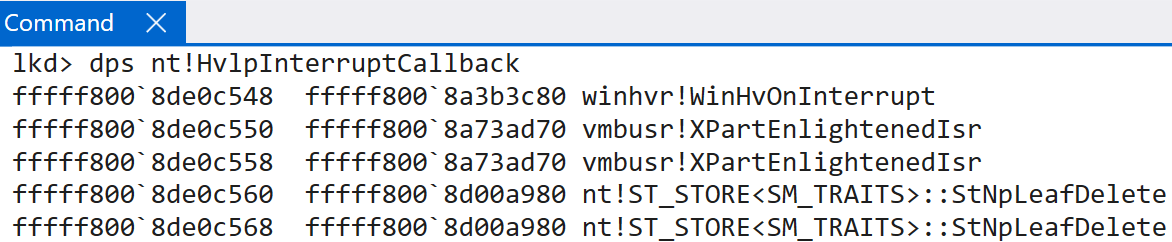
nt!HalpInterruptSintService then invokes nt!HvlpSintInterruptRoutine, which uses the vector value (subtracting 768 — i.e., 0x300, removing the IRQL of 3 masked into the vector) to index the nt!HvlpInterruptCallback table. Note that NtNpLeafDelete appears as a side effect of symbol collision: for functions with identical code, the symbols get mashed into one. These two functions are simply ret NO-OP operations.
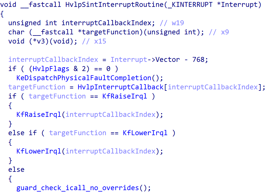
nt!HvlpSintInterruptRoutine dispatch table. Source: original article.There are 5 total valid entries here (vector values 0x300 through 0x304 use this service routine, so the valid indexes are 0–4 — 5 entries). Even Windows Internals, 7th Edition, Part 2 calls out that “vectors 30–34 are always used for Hyper-V related [VMBus] interrupts”. Technically, index 0 (0x300) is used for hypervisor interrupts and indexes 1–4 are used for VMBus interrupts. One important thing: if an interrupt is to arrive at a guest, it always first goes to the root partition. If the guest partition then needs the interrupt (for instance, if it has a synthetic device emulating real physical devices like a keyboard), the root partition asserts an interrupt to the guest using the VMBus protocol (used for inner-partition communication). This is also why we see such a disparity in IDTs between root partitions (the host OS) and the guest OS where the dynamic analysis is done.
Note that the below tables differ based on whether the target OS is the root or guest partition.
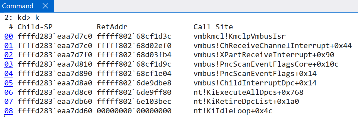
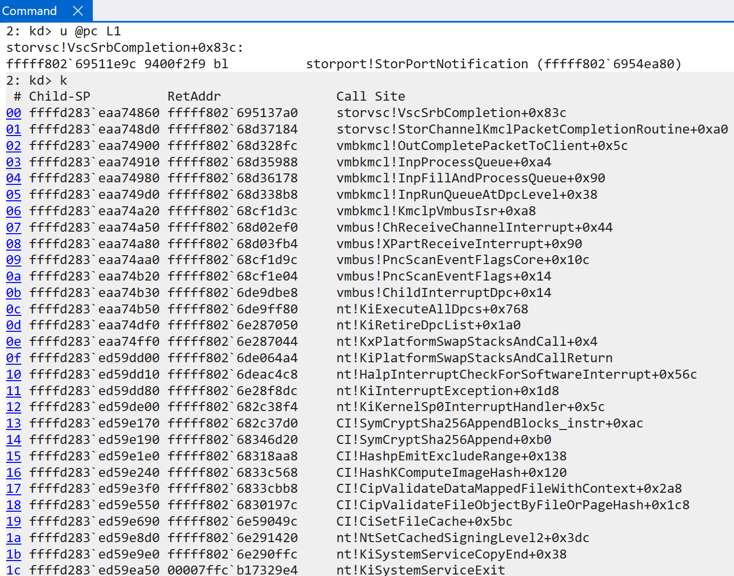
So how do child partitions receive interrupts from the root partition so that they can be sent on to the target handler? vmbus!XPartEnlightenedIsr is the main entry point. As other researchers have noted, these functions hold the functionality needed to pass the virtual interrupt to the appropriate handlers. vmbus!XPartEnlightenedIsr simply queues a DPC with the target routine vmbus!ChildInterruptDpc. That function eventually invokes vmbus!XPartReceiveInterrupt — to receive the interrupt from the root partition (or hypervisor). That, in turn, invokes the lower-level vmbus!ChReceiveChannelInterrupt, which then invokes the true ISR — vmbkmcl!KmclpVmbusIsr (or vmbkmcl!KmclpVmbusManualIsr).
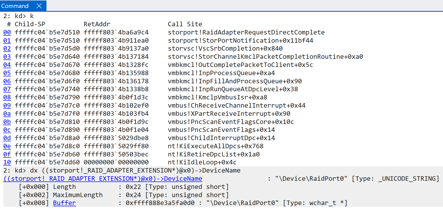
That ISR is responsible for eventually determining how to handle the interrupt from Hyper-V by parsing the message protocol. The vmbkmcl.sys driver (the VMBus common library driver) handles most of the parsing and yields the target operation. In this example, the guest receives an interrupt from the hypervisor, which results in a call to vmbkcml!InpFillAndProcessQueue — which dispatches the target. In this case, the synthetic SCSI driver (storvsc.sys) is dispatched. The request is then forwarded to the VM’s storport.sys driver, indicating that the interrupt was sent to this guest in order to notify the StorPort driver about a request that was completed (RequestDirectComplete). This particular request ended up invoking storport!RaidAdapterRequestDirectComplete, passing the associated RAID_ADAPTER_EXTENSION structure from the notification request. In conclusion, this is how the guest partition fulfils a particular request at the synthetic-device level upon request from the root partition or hypervisor as a result of some physical device interrupt.
VTLs, Secure Kernel Interrupts, and Secure Interrupts
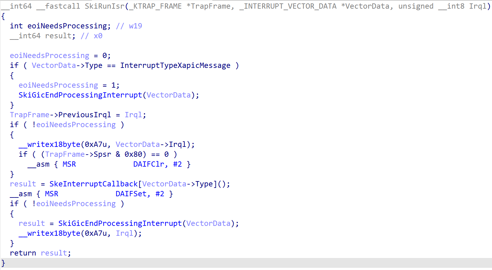
This section is not specific to ARM64, so it is brief — for completeness. It is still worth mentioning because interrupt handling in the Secure Kernel is completely different from x64 (in fact, almost all of the interrupt-related functions do not exist on x64 as they do on ARM, and vice versa). The TLFS defines that each VTL has its own virtual interrupt controller (here, that means the Secure Kernel in VTL 1 has its own virtual GIC to interface with, separate from the root partition’s virtual GIC in VTL 0 — both configured by Hyper-V). The Secure Kernel has a very similar function to NT, securekernel!SkiGicInitialize. Additionally, securekernel!SkiGicData effectively mirrors nt!HalpGic3 in NT. The main functionality in the Secure Kernel is securekernel!SkiRunIsr. That function invokes the appropriate function in the securekernel!SkeInterruptCallback table.
Although the Secure Kernel does not accept file I/O, etc., it still needs the ability to handle interrupts — because of secure interrupts and secure intercepts. Secure interrupts are interrupts trapped into VTL 1 as a result of some action in VTL 0 (thanks to the hypervisor). On ARM64 systems, the Secure Kernel is responsible for registering with the synthetic interrupt controller (securekernel!ShvlpInitializeSynic). This allows the Secure Kernel to receive a synthetic interrupt as a result of an intercept, for example. A great example of this is HyperGuard. How does this work? On the latest insider preview build of Windows, the SkeInterruptCallback table (notice the similarity to the synthetic handler routine from NT — nt!HvlpSintInterruptRoutine — both are synthetic interrupt handlers) is as follows:
ShvlpVinaHandlerShvlpTimerHandlerShvlpInterceptHandler→ the secure intercept handlerSkiHandleFreezeIpiSkiHandleCallbackSkiHandleIpi
The “secure interrupt” handler we care about is ShvlpInterceptHandler. As Yarden calls out in her blog, the intercept functionality registers with Hyper-V a list of actions to intercept. For example, certain writes or accesses to ARM64 system registers will cause Hyper-V to inject a synthetic interrupt into the Secure Kernel, allowing the Secure Kernel to examine such an operation inline as it occurs and either prevent it (causing a crash via ShvlRaiseSecureFault, for example) or let the action occur. Even other items like hypercalls can be intercepted. This is the basis for HyperGuard.
Windows on ARM Interrupts — WinDbg
Before wrapping up, a few WinDbg nuances at the time of writing. Some commands, like !idt, simply do not work because of the differences in interrupt handling. A few useful commands specific to ARM:
!gicc→ GIC CPU interface analysis!gicd→ GIC distributor analysis!gicr→ GIC redistributor analysis
Key Takeaways
- WoA uses ARM’s GICv3 / vGIC instead of Intel’s APIC; the distributor, per-CPU redistributors, CPU interfaces, and (optionally) ITS replace LAPIC / IOAPIC entirely, and Hyper-V does not expose the ITS to the root partition.
- Interrupt initialization starts in
nt!HalpInitializeInterrupts→nt!HalpGic3Discover; the MADT (ACPI “APIC” table) describes the distributor, per-CPU GICR/GICC structures, and MSI frames, and is parsed viant!ExtEnvGetAcpiTableintont!_MAPIC. - Each
KINTERRUPTcarries aVectorwhose upper byte encodes the IRQL and whose lower nibble indexes the per-CPU IDT (KPCR->Idt, with overflow intoKPCR->IdtExt) — capping the addressable space at 256 interrupts (16 IRQLs × 16 slots). - There is no IDTR-driven hardware vector dispatch on ARM. The CPU jumps to
VBAR_EL1+ a fixed offset (0x80for EL0 IRQ,0x280for EL1 IRQ,0x480for AArch64 lower-EL,0x680for AArch32 lower-EL); software then readsICC_IAR1_EL1to fetch the INTID, looks up the matchingKINTERRUPT, and callsnt!KiPlayInterruptto dispatch the ISR. - Hyper-V configures
HCR_EL2.{FMO,IMO}to enable virtual IRQs and usesICH_LR<0..15>_EL2to inject up to 16 simultaneous virtual interrupts per virtual CPU; on top of that, the synthetic interrupt controller (SINT) handlernt!HalpInterruptSintService→nt!HvlpSintInterruptRoutineuses vectors0x300–0x304to deliver hypervisor and VMBus messages. - For VBS, VTL 1’s Secure Kernel registers with the synthetic interrupt controller (
securekernel!ShvlpInitializeSynic) and dispatches viasecurekernel!SkiRunIsr/SkeInterruptCallback— withShvlpInterceptHandleras the secure intercept entry point underpinning HyperGuard. - Useful WinDbg commands on WoA:
!gicc,!gicd,!gicr; the classic!idtdoes not work.
Defensive and Research Recommendations
- Treat ARM64 WoA as a separate research target from x64 — reuse mental models for IRQLs and ISRs, but rebuild your tooling around
VBAR_EL1,ICC_IAR1_EL1,ICC_EOIR1_EL1, and the per-CPU IDT (KPCR->Idt/IdtExt) rather than IDTR-style indexing. - When triaging a suspicious driver or ISR on WoA, walk
nt!HalpRegisteredInterruptControllersand theINTERRUPT_LINESlist to confirm that registeredKINTERRUPTobjects come from expected sources — a foreignServiceRoutineon a known INTID is a strong anomaly indicator. - For Hyper-V / VBS-enabled hosts, monitor and audit synthetic-interrupt usage (
nt!HalpInterruptSintServiceregistration,HvlpInterruptCallbacktable integrity, VMBus channel registration) — this is where root↔guest and VTL 0↔VTL 1 boundary crossings happen. - For HyperGuard-aware monitoring, treat
ShvlpInterceptHandleractivity as a privileged signal: secure intercepts trigger on system-register and hypercall touches that would otherwise be invisible to NT-side telemetry. - Driver authors writing ARM64-aware kernel code must respect the 16-IRQL / 16-slot encoding in
KINTERRUPT.Vector; reusing an x64-style “I can just pick any vector below 0xFF” idiom can silently collide with an existing IDT slot. - When fuzzing or reversing the WoA interrupt path, always identify the operating environment (
_EXT_ENVvalues likeExtEnvHvRoot,ExtEnvHvGuest,ExtEnvSecureKernel): the same code path behaves differently between root, guest, and Secure Kernel contexts, and a bug that reproduces in one will not necessarily reproduce in another. - Capture symbol-collision pitfalls in your analysis (e.g.,
NtNpLeafDeleteappearing inHvlpInterruptCallback) — identical code blobs share a symbol, so chasing names without verifying disassembly will mislead you. - Keep the ARM GIC architecture specification and the ACPI 6.x MADT chapter open when reading Windows interrupt code; many fields (e.g.,
GICR_PROPBASER,GICR_PENDBASER,GICD_IROUTER) are not in the Windows symbols and require cross-referencing.
Conclusion
Windows on ARM rebuilds the interrupt stack from the ground up around the Generic Interrupt Controller: discovery moves from APIC to MADT-described GICD / GICR / GICC structures, dispatch moves from an IDTR-indexed hardware vector to a software-defined vector read through ICC_IAR1_EL1, and virtualization adds Hyper-V’s ICH_LR<N>_EL2 injection, the synthetic interrupt controller, and Secure Kernel callbacks on top. For Windows internals researchers, the encouraging news is that the high-level vocabulary survives — KINTERRUPT, IRQLs, ISRs, IPIs, IDTs — even when nearly every register, table, and dispatch path beneath it has changed.
Resources
- Matt Suiche blog: SMBaloo — Building a RCE Exploit for Windows ARM64 (SMBGhost Edition)
- UEFI / ACPI spec: ACPI Spec 6.6 (PDF)
- Microsoft: ACPI System Description Tables
- Code Machine: ARM Assembler Primer
- BSOD Tutorials: Hardware Interrupts, IRQs and IRQLs (Part 1)
- ARM GIC Specification: Arm Generic Interrupt Controller Architecture Specification
- Hyper-V internals: Hyper-V Internals
Original text: “Windows ARM64 Internals: Pardon The Interruption! Interrupts on Windows for ARM” by Connor McGarr at Connor McGarr’s Blog.